Fault tolerant control system

a control system and fault-tolerant technology, applied in the field of fault-tolerant bywire vehicle control systems, can solve the problems of reducing the availability of the system, increasing system cost and complexity, and the architecture does not address software anomalies, so as to improve fault-isolation capabilities, reduce system cost, and reduce hardware redundancy

Active Publication Date: 2012-01-17
GM GLOBAL TECH OPERATIONS LLC
View PDF11 Cites 15 Cited by
  • Summary
  • Abstract
  • Description
  • Claims
  • Application Information

AI Technical Summary

Benefits of technology

[0008]The present invention uses a novel dual-redundant propulsion-by-wire architecture with robust monitor that increase system availability without compromising safety. Dual-redundant controllers are characterized by monitors effecting cross-monitoring and self-monitoring. Self monitoring is effected at the application level and built-in system tests are performed. The monitor functions are set as high priority tasks, further increasing the level of security in the system.
[0021]The exemplary system provides benefits resulting from low levels of hardware redundancy. The diverse and robust monitors improve fault-isolation capabilities and guard against many hardware and software anomalies. The monitors combine self-check of traditional dual-redundant systems with application-specific tests and built-in-tests. Furthermore, a single fault does not result in the loss of both the front and rear propulsion systems. If the monitor on the rear controller fails silent, the front propulsion system is disabled to prevent run-away situations by a subsequent failure in the front controller. Similarly, if the monitor on the front controller fails silent, the rear propulsion system is disabled to prevent run-away situations by a subsequent failure in the rear controller. The minimal amendment of redundancy effects lower system cost, compared to the prior art.

Problems solved by technology

This behavior may be acceptable from a risk management standpoint but undesirably reduces the availability of the system.
Additionally, such architecture does not address software anomalies that may manifest in systems having identity of algorithms among controllers.
However, increased levels of hardware redundancy lead to increased system cost and complexity.
A single fault in a traditional dual-redundant PBW system (i.e., system with lowest level of redundancy) has the potential to lead to the loss of both the front and the rear (or other distribution) propulsion systems.

Method used


Image

  • Fault tolerant control system
  • Fault tolerant control system
  • Fault tolerant control system

Examples


Embodiment Construction

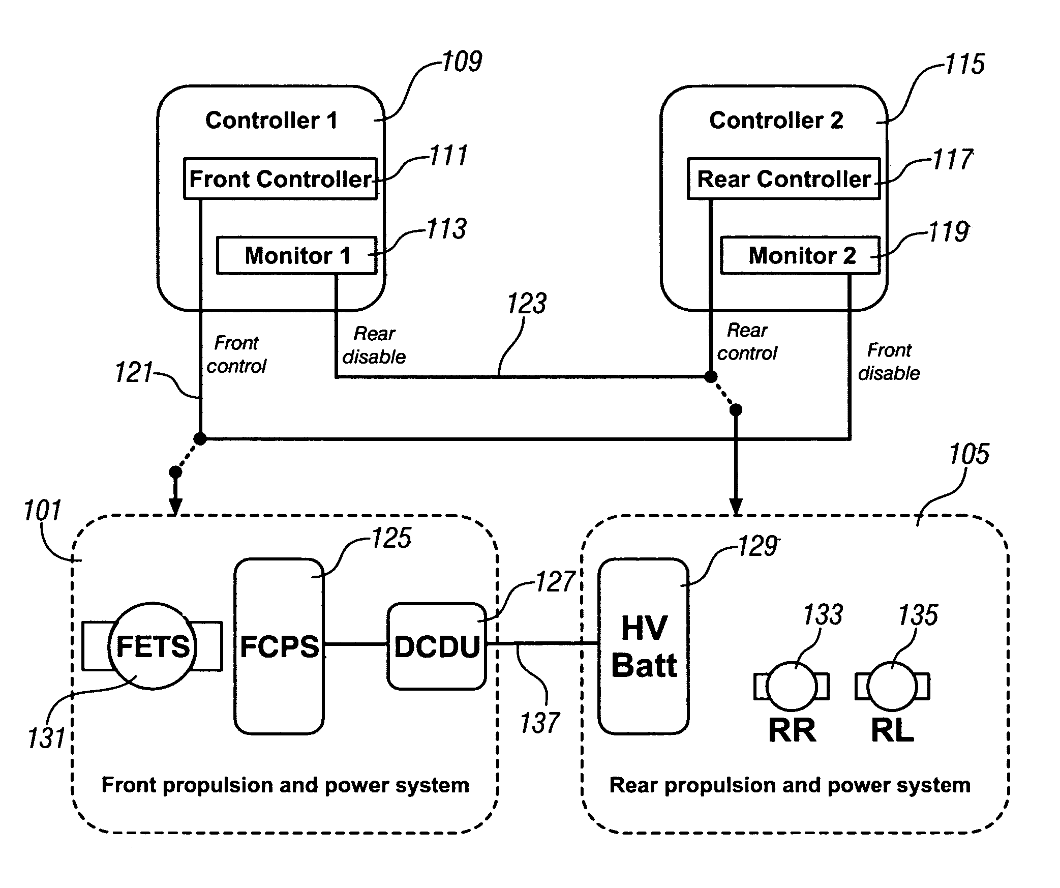
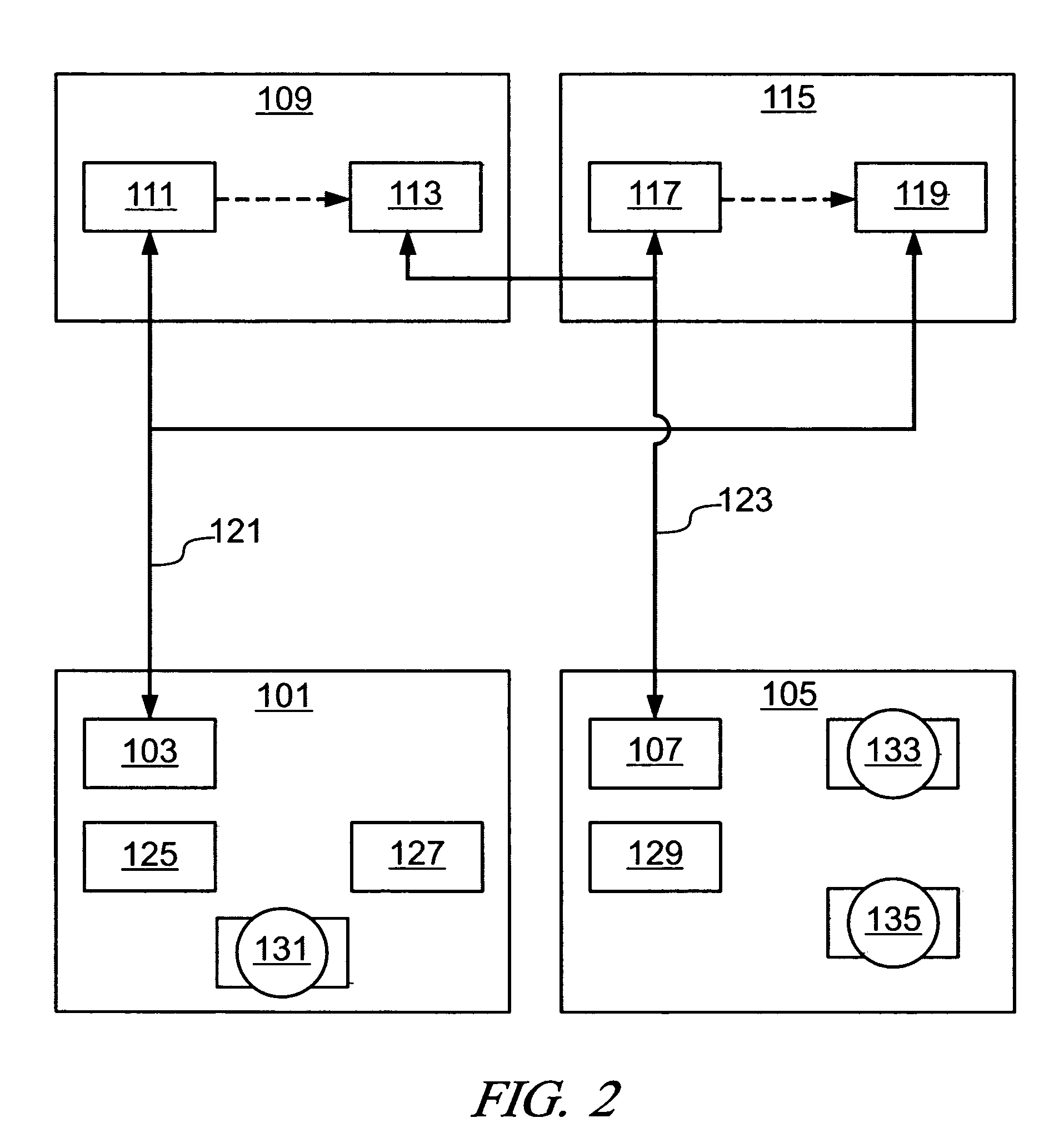
[0028]Referring now to the drawings, wherein the showings are for the purpose of illustrating the invention only and not for the purpose of limiting the same, FIG. 2 shows a schematic of an exemplary fault-tolerant control scheme which has been constructed in accordance with the present invention. The system includes a first system 101 including a first system control unit 103, and a second system 105 including a second system control unit 107. There is a first supervisory control module 109 including a first control 111 and a second system monitor 113 operable to monitor the second system 105. A second supervisory control unit 115 includes a second control 117 and a first system monitor 119 operable to monitor the first system 101. A first system control bus 121 is operatively coupled to the first control 111, the first system control, unit 103 and the first system monitor 119. A second system control bus 123 is operatively coupled to the second control 117, the second system contr...


PUM


Abstract

A dual-redundant propulsion-by-wire control architecture with robust monitoring is presented to increase system availability without compromising safety. The dual-redundant controllers are able to cross-monitor and self-monitor. Self monitoring is effected at the application level and built-in system tests are performed. The monitor functions are set as high priority tasks. The first controller controls operation of a first propulsion system, monitors operation of a second controller, and, self-monitors. The second controller controls operation of a second propulsion system, monitors operation of the first controller, and, self-monitors. Each controller is operable to identify faults occurring in the first and the second controller, and implement an alternate operating control scheme for the respective propulsion system when a fault is identified. The first controller is signally connected to the second controller by substantially redundant communications buses.

Description

CROSS-REFERENCE TO RELATED APPLICATIONS[0001]This application claims priority from U.S. Provisional Application No. 60 / 608,684 filed Sep. 10, 2004, entitled FAULT TOLERANT CONTROL SYSTEM.TECHNICAL FIELD[0002]This invention generally relates to vehicle control systems. More particularly, this invention relates to fault-tolerant by-wire vehicle control systems.BACKGROUND OF THE INVENTION[0003]Vehicle systems designers are developing numerous propulsion systems to improve energy-efficiency and reduce need for consumption of fossil fuels, including fuel / electric hybrid systems having batteries and individual wheel motors, and fuel-cell systems. Each system uses one or more electronic controllers to control ongoing operation of all or part of one or more systems related to vehicle operation and propulsion. Such vehicle systems include various by-wire control systems, each consisting of an operator-controlled input device which is connected via electric wiring harness and a controller to ...

Claims


Application Information

Patent Timeline
Patent Type & Authority Patents(United States)
IPC IPC(8): G05B11/01
CPCG05B9/03Y10S903/945Y10S903/916Y10S903/919
Inventor NAIK, SANJEEV M.MISHRA, PRADYUMNA K.PERTET, SOILA M.
Owner GM GLOBAL TECH OPERATIONS LLC
Why Eureka
Try Eureka