
Loose tube flying lead assembly

a technology of flying lead and loose tube, which is applied in the direction of sealing/packing, drilling pipes, and well accessories, etc., can solve the problems of delayed production of prior art flying, inability to support handling and installation loads, and inability to transmit loads to the frame, so as to prevent the over-hose from bunching and prevent unwanted exposure of the interior conduit

Inactive Publication Date: 2012-01-24
DEEP DOWN INC
View PDF31 Cites 23 Cited by
  • Summary
  • Abstract
  • Description
  • Claims
  • Application Information

AI Technical Summary

Benefits of technology

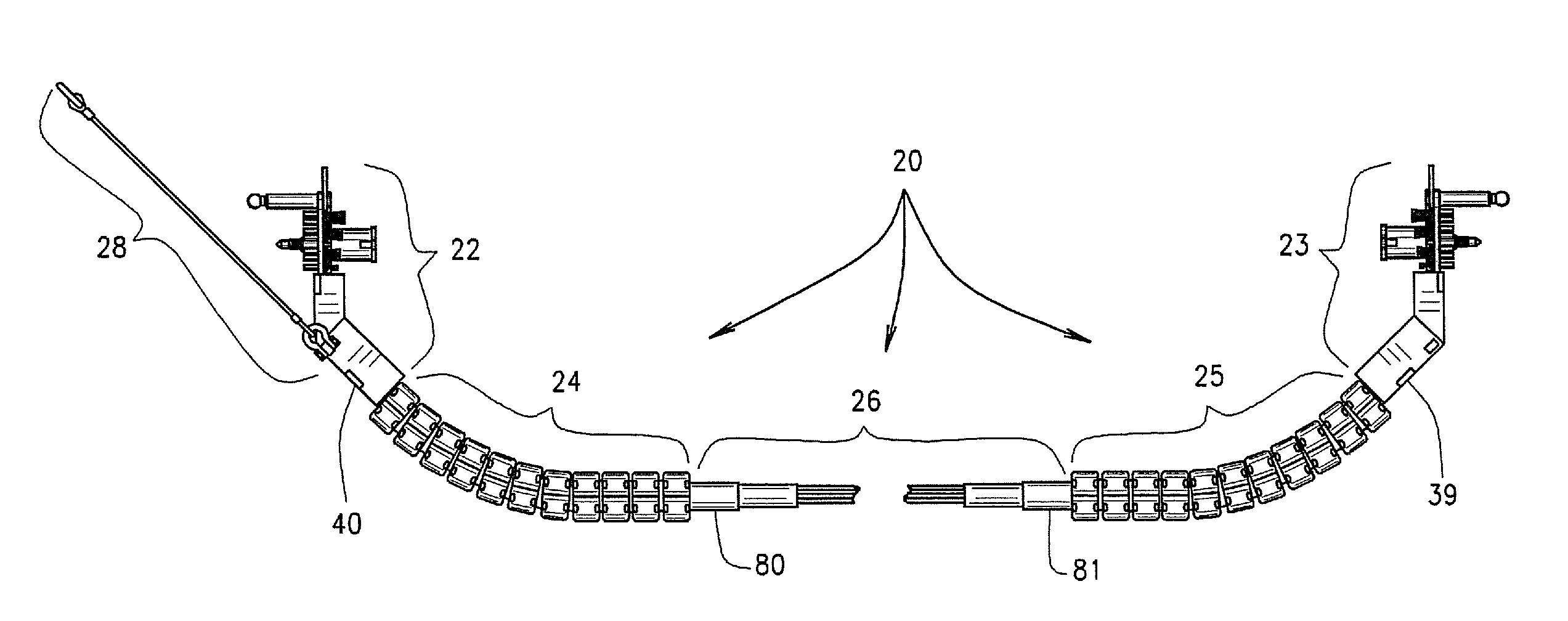
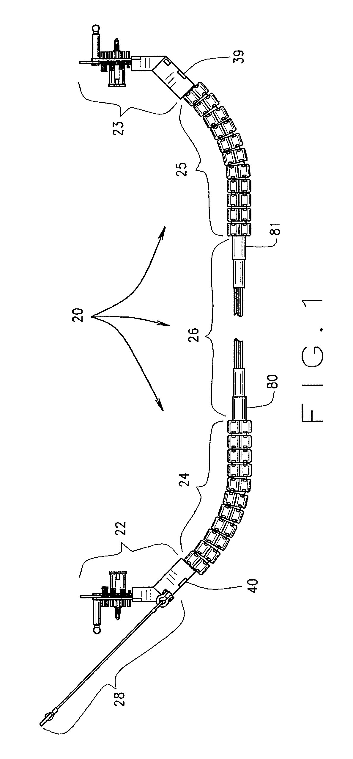
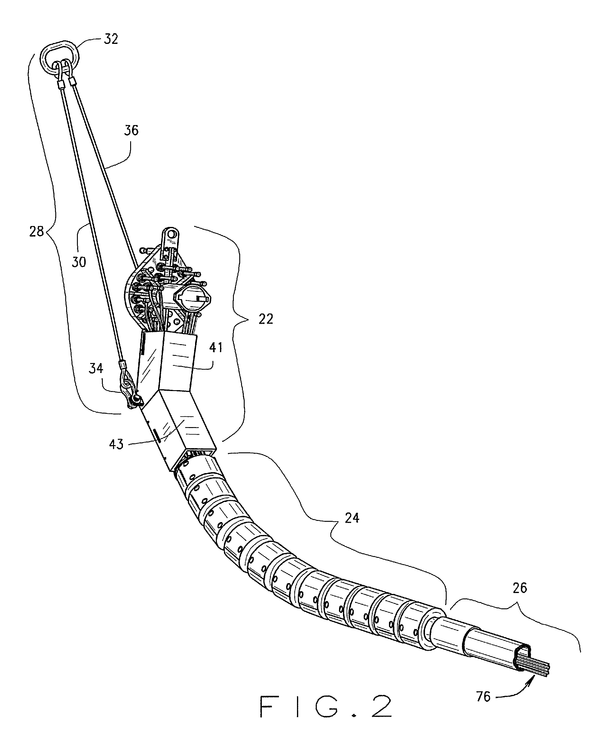
"The present invention is about a new design for flying leads used in offshore oil production. The invention includes a flying lead bundle with cobra head assemblies, bend limiter assemblies, and an elongate bundle extending between the bend limiter assemblies. The flying leads have non-constrained interior conduits that can move freely within the elongate bundle, resulting in a smaller bend radius and a smaller foot print on the installation vessel deck. The load bearing bend limiter assemblies and load bearing over-hose connectors are capable of transmitting loads of up to 10 tons to the frame. The invention allows for easier installation, reduced manufacturing costs, and shorter installation time compared to prior art flying leads."

Problems solved by technology

These design complications sometimes delayed production of prior art flying leads due to re-engineering efforts and / or required vendors to carry large inventories of specialized parts to accommodate different types of stab-plates and conduit types and configurations.
Thermoplastic hoses and cables are incapable of supporting handling and installation loads.
The bend limiter assembly of the prior art does not make a physical connection to the over hose or sheathing material surrounding the elongate conduit bundle and is incapable of transmitting loads to the frame.
Prior art over-hose and roving designs do not make a physical connection to either the prior art bend limiter assembly or the prior art frame assembly.
Prior art designs employing the over-hose may therefore bunch up during installation which can lead to exposure of the interior conduits or breaks at the splice intersections.
This can lead to abrasion and kinking of the interior conduits at the bend limiter interface and splice intersections.
This type of prior art hose is subject to UV degradation and chemical attack both of which are common in most oilfield applications.
A disadvantage associated with prior art flying leads using thermoplastic hoses is premature rupture and shorter design life spans than project design.
Using prior art designs it is difficult to service the flying lead on the deck of a ship.
Epoxy terminated prior art steel tube flying leads are not serviceable on the deck of a ship; they have to be sent back to the manufacture for refurbishment.
Another disadvantage associated with the prior art epoxy termination is the fact that the epoxy termination is manufactured from steel, is significantly larger and heavier than the present invention.
The added weight and length from the prior art epoxy termination tends to complicate the installation and requires additional buoyancy to lift the cobra head during installation.
This fact along with the dense materials used for construction of the elongate bundle and interior conduits make the elongate bundle negatively buoyant in both designs.
However, there is a disadvantage associated with this feature in the prior art.
These protrusions increase the risk of damage to the flying lead and other components during work-over and follow-on installation operations.
This often breaks an over-hose splice or pulls the hose away from the second end.

Method used


Image

  • Loose tube flying lead assembly
  • Loose tube flying lead assembly
  • Loose tube flying lead assembly

Examples


embodiment 276

[0098]FIG. 15 is an alternative embodiment 276 of the interface element for a stab-plate produced by FMC® Technologies, not shown. The interface element 276 has a left lug 272 sized and arranged to engage the left slot 45 in the universal frame 40. The interface element 276 also has a right lug 274, sized and arranged to engage the right slot 47 in the universal frame 40. The interface element 276 has a plurality of holes 278, 280, 284 and 886 sized and arranged to engage the FMC stab-plate, not shown.

embodiment 300

[0099]FIG. 16 is an alternative embodiment 300 of the interface element for a stab-plate produced by Unitech, not shown. The interface element 300 has a left lug 272 sized and arranged to engage the left slot 45 in the universal frame 40. The interface element 300 also has a right lug 274, sized and arranged to engage the right slot 47 in the universal frame 40. The interface element 300 has a plurality of holes 302, 304, 306 and 308 sized and arranged to engage the Unitech stab-plate, not shown.

embodiment 320

[0100]FIG. 17 and 18 is an alternative embodiment 320 of the interface element for a stab-plate produced by Oceaneering, not shown. The interface element 320 may be fabricated as a single component, or for simplicity it may be fabricated from three components, 322, 324, and 324. The interface element 320 has a left lug 272 sized and arranged to engage the left slot 45 in the universal frame 40. The interface element 320 also has a right lug 274, sized and arranged to engage the right slot 47 in the universal frame 40. The interface element has a plurality of holes 328, 330 and 332 and a fourth hole, not shown, sized and arranged to engage the Oceaneering stab-plate, not shown.


PUM


Abstract

In combination, the loose tube flying lead includes: a) a pair of improved cobra head assemblies, each being able to receive a variety of different stab-plates with minimal modification; b) a pair of bend limiters, one extending from each cobra head assembly and c) an elongate bundle of non-constrained interior conduits surrounded by an over-hose, the over-hose being connected to each bend limiter. The over-hose may rotate independently of the bend limiters and the cobra head assemblies.

Description

DESCRIPTION OF THE PRIOR ART[0001]The terms “umbilical,”“jumper” and / or “flying lead” are not always used with precision in the oil and gas industry or in the literature. For example, claim 1 of U.S. Pat. No. 6,102,124 describes a “flying lead hydraulic umbilical.” U.S. Pat. No. 6,957,929 also uses the two terms interchangeably. Each of these devices, properly understood, is distinct in both design and application. We therefore intend to distinguish and define these terms with greater precision herein.[0002]A. Umbilicals[0003]For purposes of this application an “umbilical” is defined as a composite structure composed of a multitude of conduits sheathed in an outer jacket of some form, generally including some combination of steel tubes, thermoplastic hoses, electric cables, fiber optic cables and / or fillers for use in subsea exploration and production of oil and gas. Umbilicals extend from either a) a host on the ocean surface or on land to a subsea distribution point or b) from one...

Claims


Application Information

Patent Timeline
Patent Type & Authority Patents(United States)
IPC IPC(8): E21B43/01
CPCE21B17/017E21B43/013
Inventor SMITH, RONALD E.THEOBALD, JOHN
Owner DEEP DOWN INC
Learn More