Fuel injector with fuel pressure sensor

a technology of fuel injector and pressure sensor, which is applied in the direction of machines/engines, liquid transfer devices, instruments, etc., can solve the problems of reducing the accuracy of determining the pressure of fuel or a change in the pressure of fuel, and reducing the efficiency of fuel injectors, so as to achieve the desired accuracy in measuring the pressure of fuel and improve productivity

Active Publication Date: 2012-01-24
DENSO CORP
View PDF50 Cites 19 Cited by
  • Summary
  • Abstract
  • Description
  • Claims
  • Application Information

AI Technical Summary

Benefits of technology

[0009]It is, therefore, an object of the invention to provide a fuel injector which is equipped with a fuel pressure-sensing mechanism assembled integrally with a body of the fuel injector and designed to be have enhanced productivity and ensure a desired accuracy in measuring the pressure of fuel in the fuel injector.
[0010]It is another object of the invention to provide a fuel injector equipped with a fuel pressure-sensing mechanism which is easy to replace.
[0012]Specifically, the head body equipped with the fuel pressure sensor is installed on a portion of the injector body which is located far from the spray hole, thus facilitating the diagnosis of the operation of the fuel pressure sensor before the head body is fixed to the injector body. If a failure in the operation is found, it may be replaced easily, thereby improving the fabrication yield of the fuel injector.
[0013]In the preferred mode of the invention, the fuel injector further comprises a nozzle needle which is movable in an axial direction of the injector body to open and close the spray hole selectively, an actuator working to control movement of the nozzle needle in the axial direction of the injector body, and a pressure control chamber into or from which the fuel is fed or discharged by an operation of the actuator and which exerts pressure of the fuel, as fed thereinto, on a control piston to urge the nozzle needle in a valve-closing direction in which the spray hole is closed. The nozzle needle, the actuator, the control piston, and the pressure chamber are disposed in the injector body. The first end portion of the injector body to which the head body is joined is located farther from the spray hole than the pressure control chamber. This structure facilitates the laying out of signal conductors connecting with the sensing device in the head body.
[0014]The first end portion of the injector body has a first end surface, a recess formed in the first end surface to have a given depth, and a branch path which diverges from the fuel flow path and opens on a portion of the recess. The head body includes a base which has a fitting surface which is fitted to the first end surface and a protrusion which includes a portion of the fitting surface and is contoured to conform with contour of the recess. Specifically, the protrusion serves as a guide to guide the alignment of the head body with the injector body when the head body is joined to the injector body.
[0024]Specifically, the fuel pressure-sensing unit equipped with a fuel pressure sensor made up of the diaphragm and the sensing device is installed on a portion of the injector body which is located far from the spray hole, thus facilitating the diagnosis of the operation of the fuel pressure sensor before the head body is fixed to the injector body. If a failure in the operation is found, it may be replaced easily, thereby improving the fabrication yield of the fuel injector to enhance the productivity thereof.

Problems solved by technology

The systems taught in the above first to third publications, however, have a difficulty in determining the pressure of fuel supplied to each fuel injector.
It is, therefore, difficult to control the thickness of the bottom wall (i.e., a diaphragm) of the recess precisely, which may result in a decrease in accuracy in determining the pressure of fuel or a change in pressure of the fuel.
Fuel injectors, such as the ones in the first to third publications, designed to spray the fuel at high pressures are generally needed to have an injector body made of a high-hardness metal or an increased thickness of the wall of the fuel flow path in order to withstand the high-pressure fuel and thus have a pronounced problem with the difficulty in controlling the thickness of the diaphragm, in other words, ensuring a desired accuracy in measuring the pressure of fuel in the fuel injector.

Method used


Image

  • Fuel injector with fuel pressure sensor
  • Fuel injector with fuel pressure sensor
  • Fuel injector with fuel pressure sensor

Examples


second embodiment

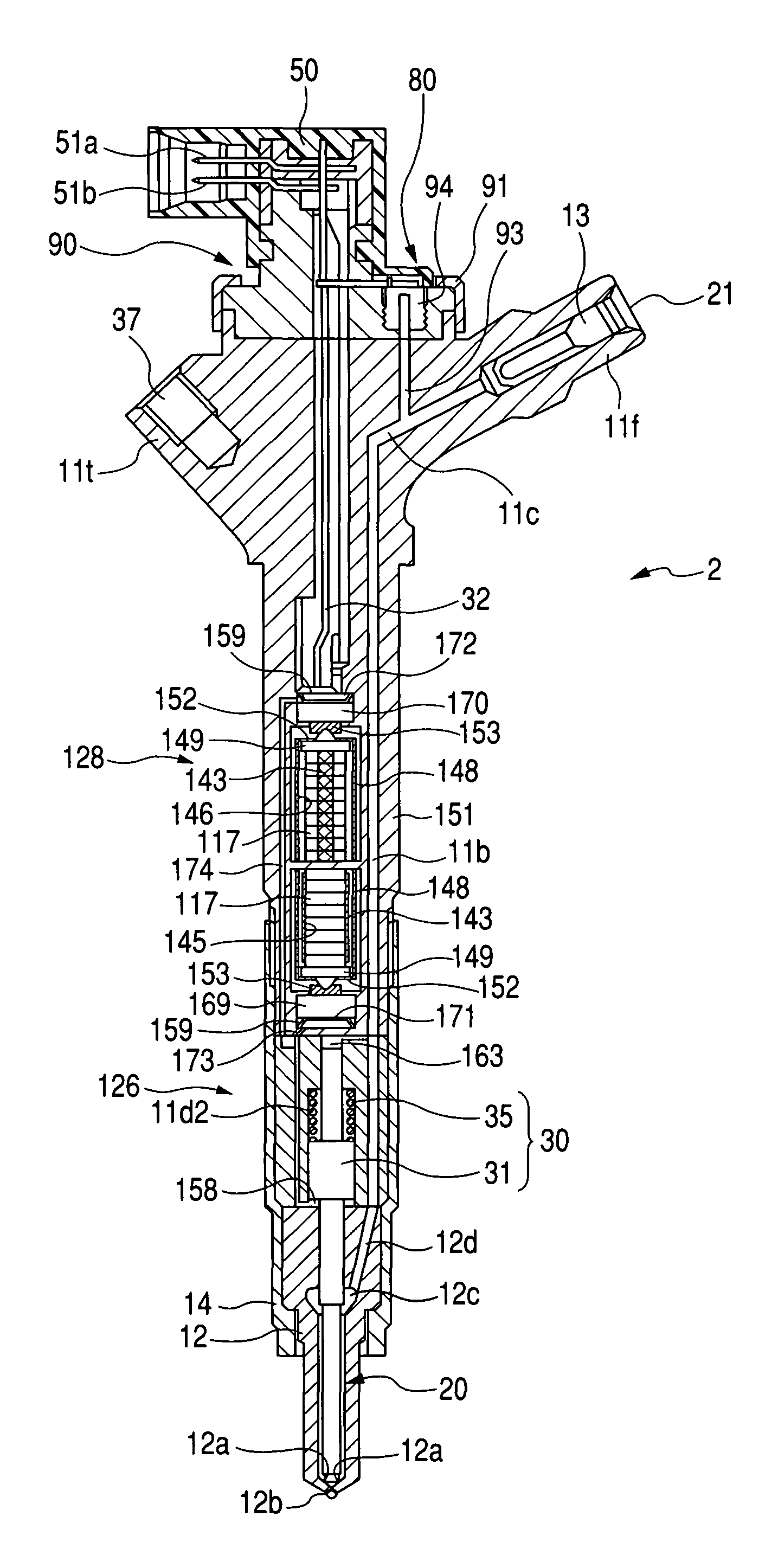
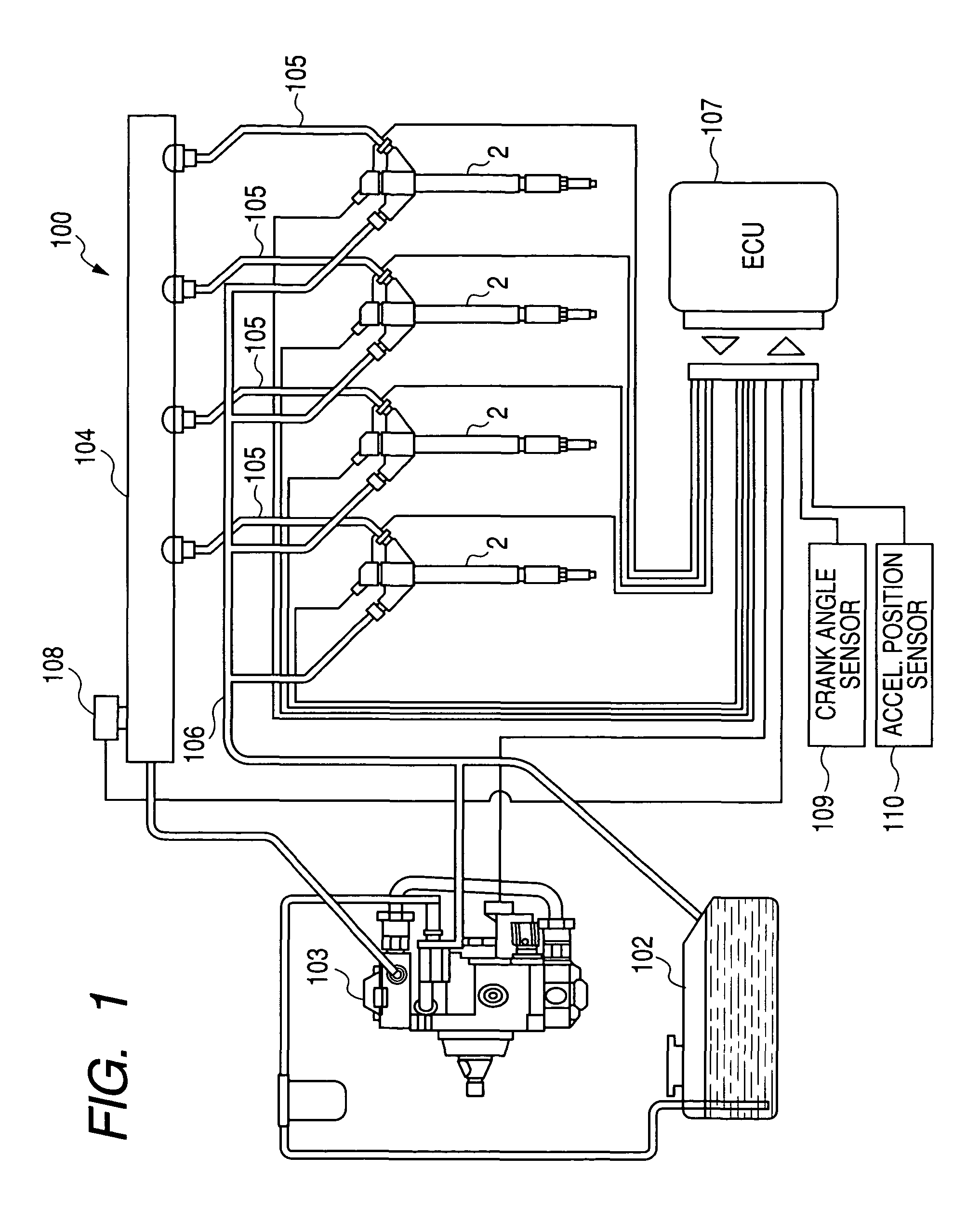
[0086]The fuel injectors 2 of the second embodiment will be described below with reference to FIGS. 7 and 8 which may be employed in the accumulator fuel injection system 100 of FIG. 1. The same reference numbers, as employed in the above embodiment, will refer to the same parts, and explanation thereof in detail will be omitted here.

first embodiment

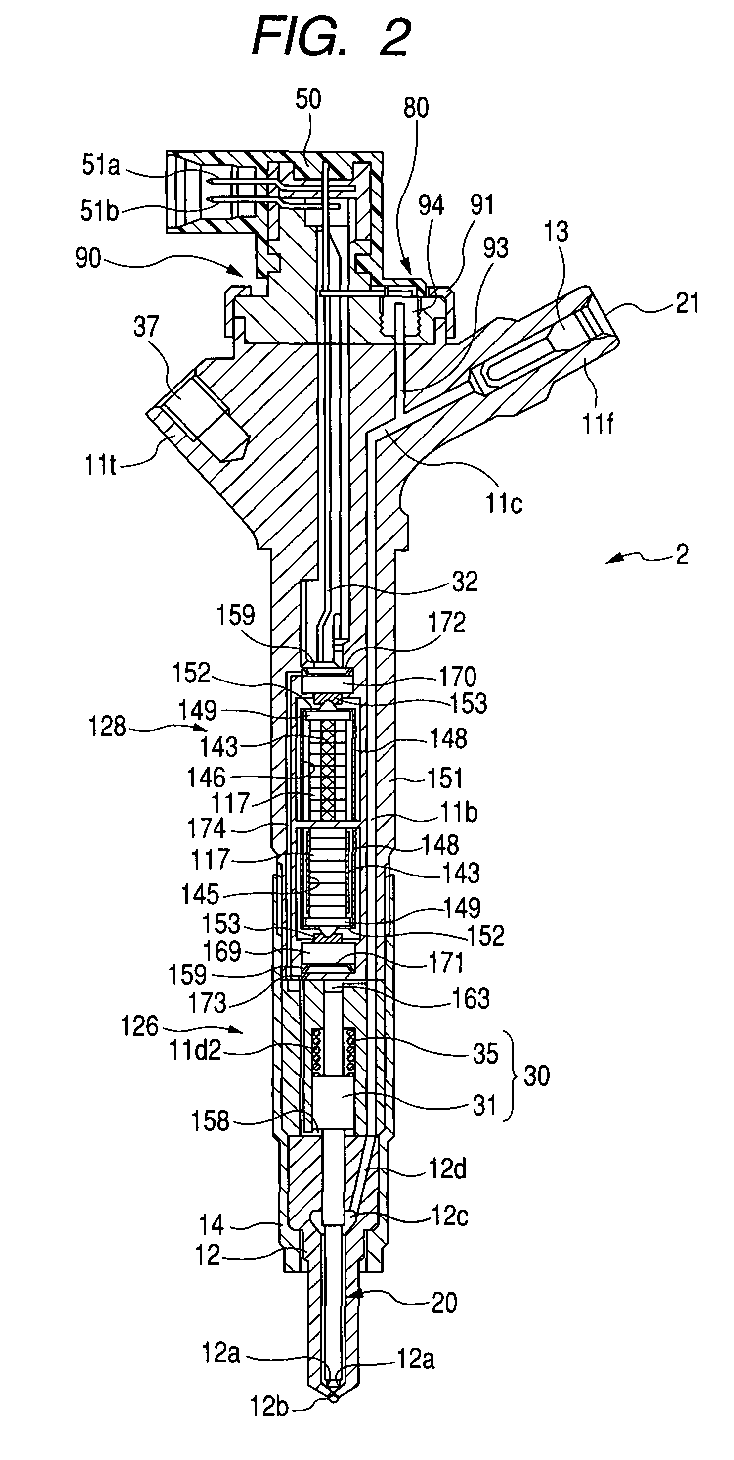
[0087]The structure of the fuel injector 2 is different from that in the first embodiment in that the metal stem 94 is installed through the base of the head body 90 threadably in the upper end of the injector body.

[0088]Specifically, the injector body has a cylindrical hole 11i formed in the upper end thereof. The cylindrical hole 11i has a depth shorter than the length of the metal stem 94 and defines a portion of a sensor mount chamber in which the metal stem 94 is disposed. The hole 11i has an internal thread formed on an inner circumference thereof. The branch path 93 extends from the bottom of the hole 11i to the fuel inlet path 11c.

[0089]The head body 90 has a cylindrical hole 95a formed through the thickness of the base thereof. The hole 95a defines the sensor mount chamber together with the cylindrical hole 11i of the injector body. The installation of the metal stem 94 in the injector body is achieved by inserting the metal stern 94 into the hole 95a and screwing it into ...

third embodiment

[0092]The fuel injectors 2 of the third embodiment will be described below with reference to FIG. 9 which may be employed in the accumulator fuel injection system 100 of FIG. 1. The same reference numbers, as employed in the above embodiments, will refer to the same parts, and explanation thereof in detail will be omitted here.

[0093]The fuel injector 2 of the first embodiment is designed to have the head body 90 attached detachably to the upper end of the injector body (i.e., the actuator body 151) and the fuel pressure sensor 80 installed in the head body 90. Specifically, an assembly of the head body 90, the metal stem 94, and the pressure sensor chip 18f is prepared and then secured to the actuator body 151. In contrast, the fuel injector 2 of the third embodiment is designed not to have the head body 90, but to have a fuel pressure-sensing unit 940 made up of the metal stem 94 and the pressure sensor chip 18f.

[0094]The actuator body 151 has a cylindrical boss 151a formed on the...


PUM


Abstract

A fuel injector which may be employed in injecting fuel into an internal combustion engine. The fuel injector includes an injector body and a head body formed to be separate from the injector body. The head body has installed therein a fuel pressure sensor working to measure the pressure of fuel in the fuel injector and is joined detachably to the injector body. The fuel injector alternatively includes an injector body and a fuel pressure-sensing unit equipped with a fuel pressure sensor. The fuel pressure-sensing unit is installed detachably on the injector body. This structure provides enhanced productivity of the fuel injector and facilitate the ease of replacement of the fuel pressure sensor.

Description

CROSS REFERENCE TO RELATED DOCUMENT[0001]The present application claims the benefit of Japanese Patent Applications No. 2008-106015 filed on Apr. 15, 2008 and No. 2009-9935 filed on Jan. 20, 2009, disclosures of which are incorporated herein by reference.BACKGROUND OF THE INVENTION[0002]1. Technical Field of the Invention[0003]The present invention relates generally to a fuel injector which may be employed in injecting fuel into an internal combustion engine, and more particularly to such a fuel injector which is equipped with a fuel pressure sensing mechanism secured integrally with a body of the fuel injector.[0004]2. Background Art[0005]Japanese Patent First Publication No. 2007-231770 discloses a common rail fuel injection system equipped with a pressure sensor working to measure the pressure of fuel to be injected into an internal combustion engine. The pressure sensor is installed in an end of a common rail to measure the pressure of fuel stored in the common rail. Typical fue...

Claims


Application Information

Patent Timeline
Patent Type & Authority Patents(United States)
IPC IPC(8): B67D7/56
CPCF02M47/027F02M57/00F02M57/005F02M61/168G01L23/10F02M2200/24F02M2200/8076F02M2200/247
Inventor KONDO, JUNYAMANAKA, AKITOSHI
Owner DENSO CORP
Why Eureka
Try Eureka