
Non-volatile memory monitor

a non-volatile memory and monitor technology, applied in static storage, digital storage, instruments, etc., can solve the problems of affecting erasure or corruption of data stored in nvm cells, and sometimes hampered programming, so as to improve the monitoring of non-volatile memory cells, improve the accuracy of nvm circuits, and improve the effect of nvm circuits

Active Publication Date: 2012-01-24
TRIUNE IP
View PDF2 Cites 19 Cited by
  • Summary
  • Abstract
  • Description
  • Claims
  • Application Information

AI Technical Summary

Benefits of technology

"The present invention provides new methods and apparatus for monitoring non-volatile memory circuits. The invention allows for efficient monitoring of the memory devices by switching between an evaluation state and a power-saving normal operating state. The monitoring system can provide an output signal in the form of a value or state reporting, or feedback into the system. The invention has advantages such as improved monitoring accuracy, rapid programming, and stability over a range of operating conditions. It is designed to require low power and is easy to manufacture."

Problems solved by technology

Despite its name, however, the non-volatile memory cell is not perfectly non-volatile in nature.
Even partial charge decay may result in erasure or corruption of the data stored in the NVM cell.
Additionally, as the electrons leak from the floating gate, the threshold voltage of the NVM cell gradually decreases, which may eventually allow a current flow sufficient to inadvertently turn a programmed cell on when a read voltage is applied.
In addition to the gradual decay of charge on the floating gate, programming is also sometimes hampered by an initial loss of charge shortly after programming.
Such charge shifts may be caused by material defects or unintended charge transfer due to circuit geometry.
Constant monitoring in order to verify retention is not only inefficient, but contradictory to the purpose of NVM, which is designed for data storage absent ongoing power input.
Another approach for addressing the problem, simply assuming retention and not monitoring or refreshing the NVM, is sometimes used, but this approach is not desirable in applications where either accuracy or reliability are highly important, particularly automotive, medical, and military markets, for example.
One of the problems with traditional voltage references is that in order to maintain a relatively constant voltage over time, the circuit requires a continuous draw of current, which is a disadvantage for low-power systems.
A problem with refresh schemes that rely solely on timer triggers is that retention may be adversely affected by events other than the passage of time.
Operating conditions, such as temperature or radiation exposure, for example, may diminish retention by stimulating electron migration or by causing changes in characteristics of the circuit that permanently affect subsequent retention.

Method used


Image

  • Non-volatile memory monitor
  • Non-volatile memory monitor
  • Non-volatile memory monitor

Examples


Embodiment Construction

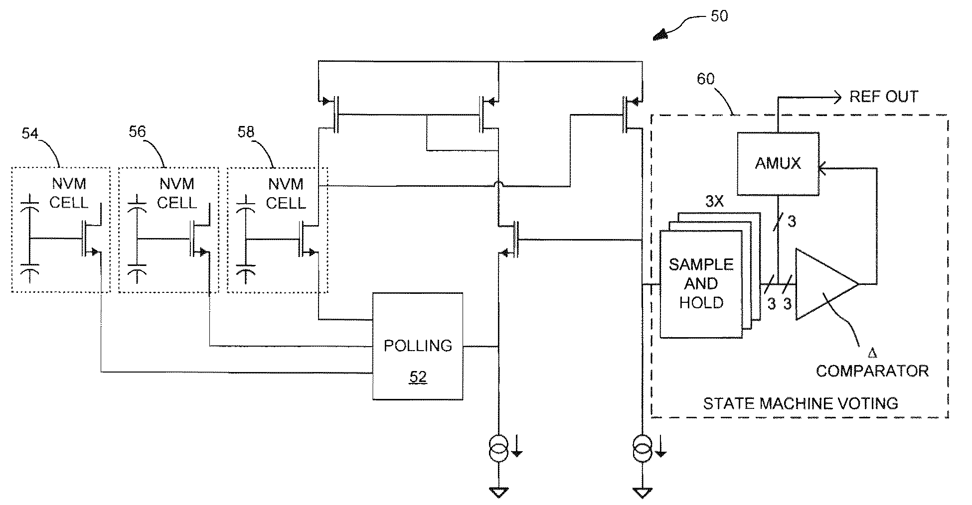
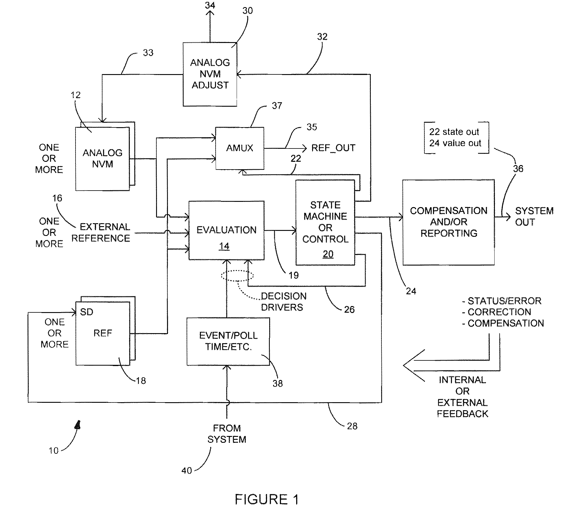
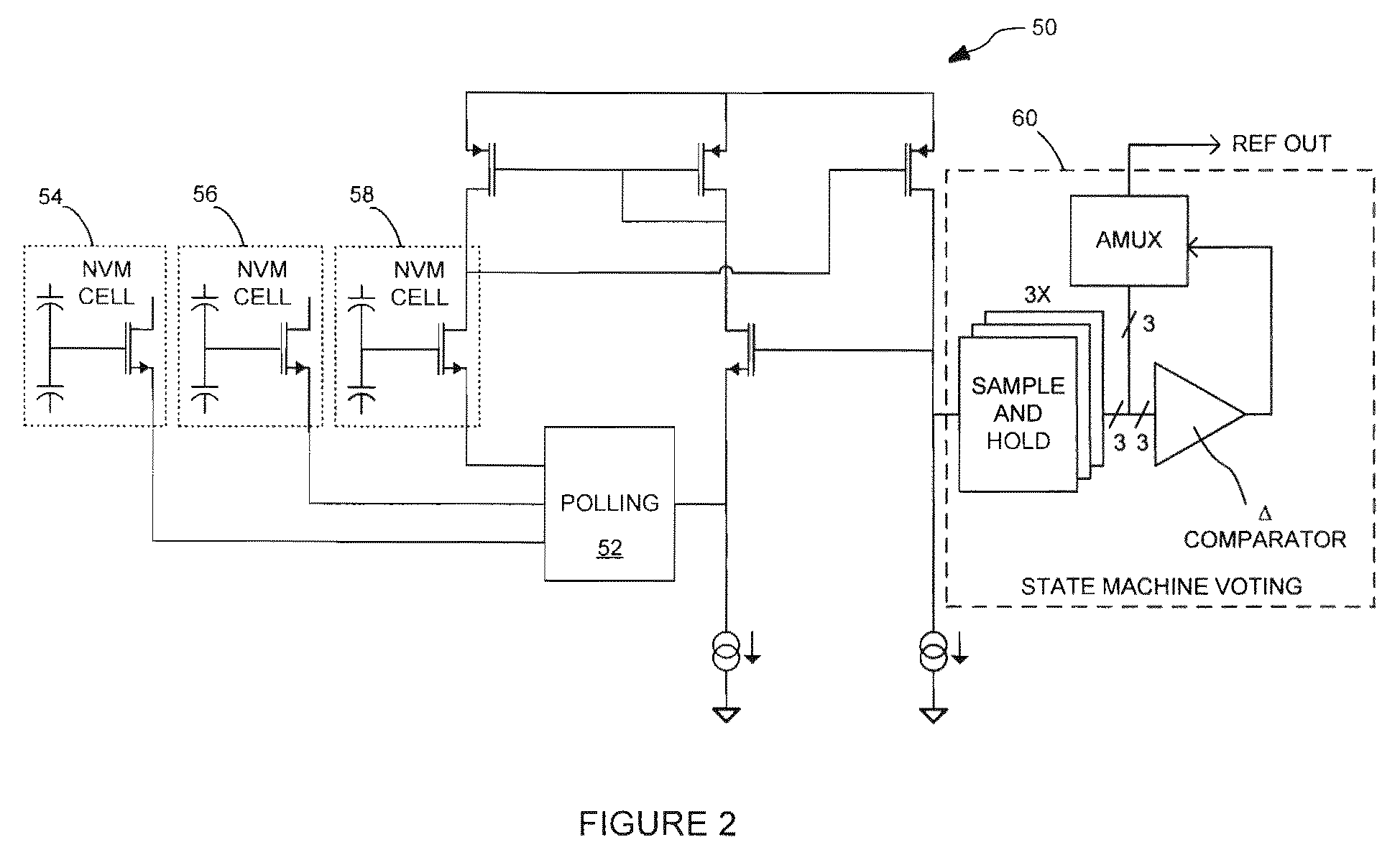
[0020]While the making and using of various exemplary embodiments of the invention are discussed herein, it should be appreciated that the present invention provides inventive concepts which can be embodied in a wide variety of specific contexts. It should be understood that the invention may be practiced with various electronic circuits, microelectronic circuit components, systems, system components, and subsystems without altering the principles of the invention. For purposes of clarity, detailed descriptions of functions, components, and systems familiar to those skilled in the applicable arts are not included. In general, the invention provides low-power non-volatile memory (NVM) monitoring circuits, systems, and methods for the improvement of non-volatile memory in a variety of applications and systems.

[0021]In implementing preferred embodiments of the present invention, one or more non-volatile memory (NVM) monitoring circuits or components may be utilized, either integrated i...


PUM


Abstract

The invention provides circuits, systems, and methods for monitoring a non-volatile memory (NVM) cell, or an array of NVM cells. The monitor is capable of switching from a normal operating state to an evaluation state, monitoring for one or more particular characteristics, and returning to the normal operating state. Alternative embodiments of the invention are disclosed using various triggers and producing outputs capable of reporting or feeding back to influence the operation of the monitoring systems and methods, the NVM circuitry, or an external system. The invention includes an energy conservation feature, in that no power is consumed in the normal operating state, and low power in the evaluation state.

Description

PRIORITY ENTITLEMENT[0001]This application is entitled to priority based on Provisional Patent Application Ser. No. 61 / 086,077 filed on Aug. 4, 2008, which is incorporated herein for all purposes by this reference. This application and the Provisional patent application have at least one common inventor.TECHNICAL FIELD[0002]The invention relates to low-current analog integrated circuitry. More particularly, the invention relates to microelectronic floating gate circuit architectures, systems, and methods for their monitoring, programming, verification, and operation.BACKGROUND OF THE INVENTION[0003]A floating gate transistor typically includes a control gate and a floating gate, such that, when provided an electrical charge through channel-hot-carrier (CHC) electron injection or Fowler-Nordheim tunneling, for example, the charge is retained on the floating gate due to isolation by a surrounding insulating oxide. Floating gate transistors are capable of storing an electrical charge f...

Claims


Application Information

Patent Timeline
Patent Type & Authority Patents(United States)
IPC IPC(8): G11C16/04
CPCG11C16/26
Inventor TEGGATZ, ROSS E.CHEN, WAYNE T.SMITH, BRETT
Owner TRIUNE IP
Learn More