Self-aligned method for fabricating a high density GMR read element

a gmr read element, self-aligning technology, applied in the direction of manufacturing tools, instruments, record information storage, etc., can solve the problem of negative affecting the performance of the read sensor

Inactive Publication Date: 2012-01-31
WESTERN DIGITAL TECH INC
View PDF4 Cites 154 Cited by
  • Summary
  • Abstract
  • Description
  • Claims
  • Application Information

AI Technical Summary

Benefits of technology

[0011]In some embodiments, forming the hard bias layer includes forming multiple layers of hard magnetic materials which can include depositing layers of chromium and depositing a layer of CoPt over the chromium layers. In some embodiments, forming the protective layer includes depositing a layer of tantalum, which can include depositing approximately 100 Å of tantalum at a high angle, such as approximately 23°,

Problems solved by technology

However, any misalignment of the mask translates into a misalignment of the ele

Method used


Image

  • Self-aligned method for fabricating a high density GMR read element
  • Self-aligned method for fabricating a high density GMR read element
  • Self-aligned method for fabricating a high density GMR read element

Examples


Embodiment Construction

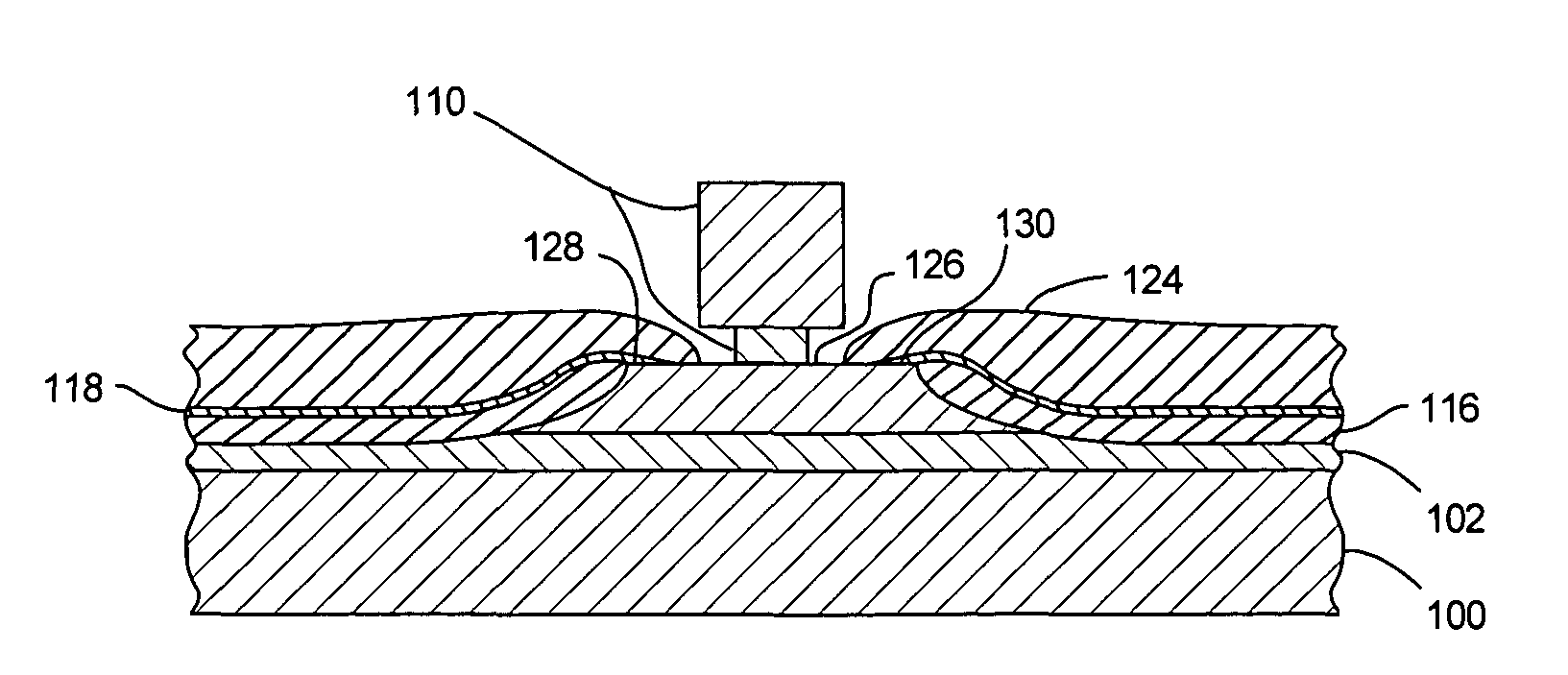
[0017]The present invention provides a method for fabricating a read element with leads that overlay a top surface of a sensor. The method includes forming a mask over a sensor layer, then using the mask to define the sensor from the sensor layer. The mask is then narrowed, for example, by static ion beam etching. Thereafter, a lead layer is formed. The narrower mask prevents the lead layer from covering the entire top surface of the sensor while allowing the lead layer to be formed such that it overlays both ends of the top surface.

[0018]FIG. 4 is a cross-section of a partially fabricated read element. While the invention can be used to form a single read element, it can also be employed in a batch process to simultaneously form a plurality of read elements. Accordingly, to achieve the partially fabricated read element of FIG. 4, a shield layer 100 is preferably formed on a substrate such as a silicon wafer (not shown). A gap layer 102 is formed above the shield layer 100, and a se...


PUM

PropertyMeasurementUnit
Fractionaaaaaaaaaa
Fractionaaaaaaaaaa
Angleaaaaaaaaaa

Abstract

A method is provided for fabricating a read element with leads that overlay a top surface of a sensor of the read element. The method includes forming a mask over a sensor layer, then using the mask to define the sensor from the sensor layer. The mask is then narrowed and a lead layer is formed that overlays both ends of the top surface of the sensor without covering a center portion of the top surface.

Description

BACKGROUND OF THE INVENTION[0001]1. Field of the Invention[0002]The present invention relates generally to the field of magnetic disk drives, and more particularly to a method for manufacturing read sensors for magnetic disk drives.[0003]2. Description of the Prior Art[0004]Magnetic disk drives are used to store and retrieve data for digital electronic apparatuses such as computers. In FIGS. 1 and 2, a magnetic disk data storage system 10 includes a sealed enclosure 12, a disk drive motor 14, and a magnetic disk, or media, 16 supported for rotation by a drive spindle 17 of motor 14. Also included are an actuator 18 and an arm 20 attached to an actuator spindle 21 of actuator 18. A suspension 22 is coupled at one end to the arm 20 and at another end to a read / write head 24. The suspension 22 and the read / write head 24 are commonly collectively referred to as a head gimbal assembly (HGA). The read / write head 24 typically includes an inductive write element and a magnetoresistive read ...

Claims


Application Information

Patent Timeline
IPC IPC(8): G11B5/127H04R31/00
CPCB82Y25/00G01R33/093G11B5/3163G11B5/398Y10T29/49044Y10T29/49052Y10T29/49043Y10T29/49046Y10T29/49048
Inventor ZHANG, JINQIUZHAO, MINGKROUNBI, MOHAMAD T.YUAN, HENRYWANG, LIEN-CHANG
Owner WESTERN DIGITAL TECH INC
Why Eureka
Try Eureka