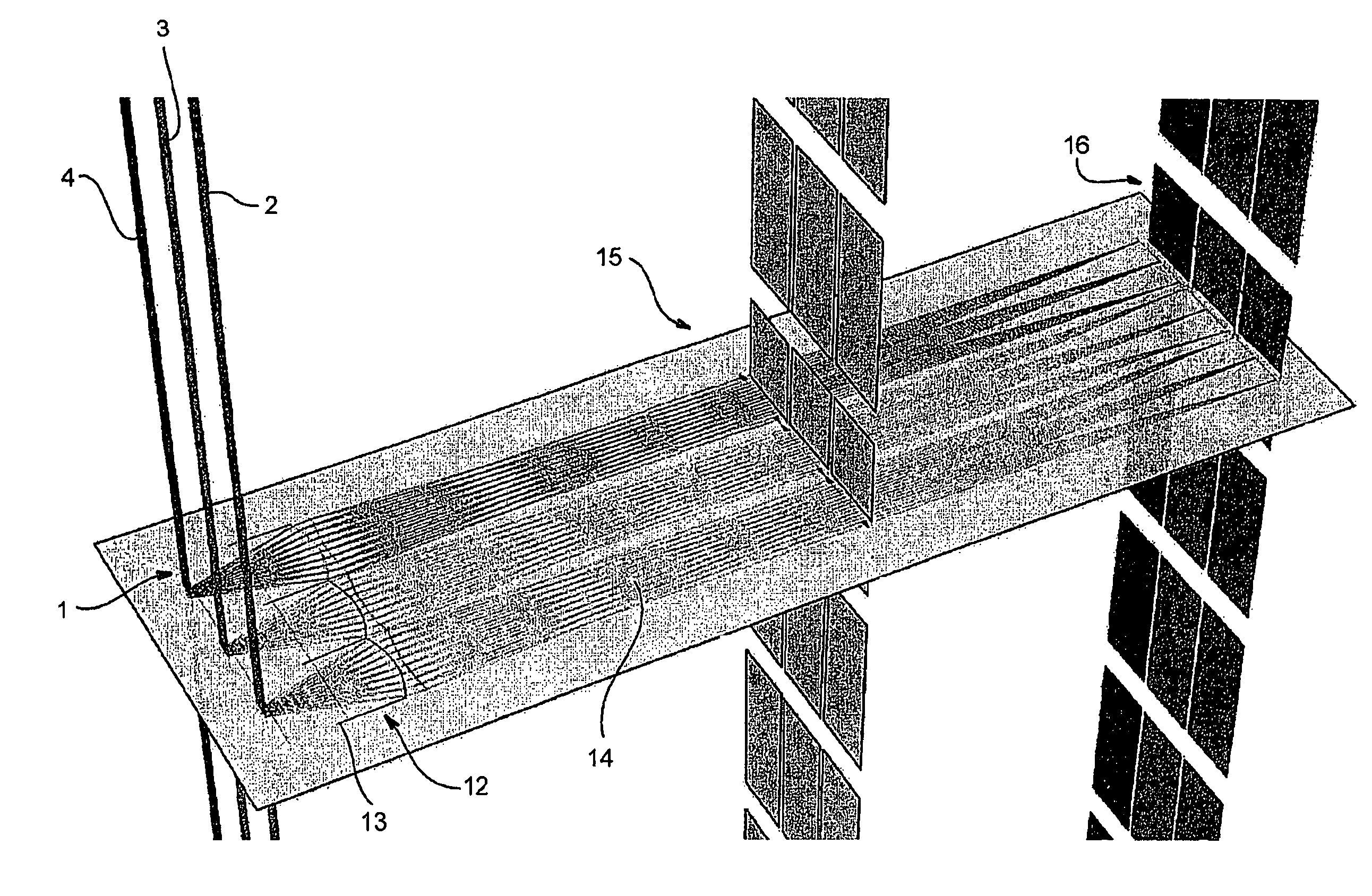
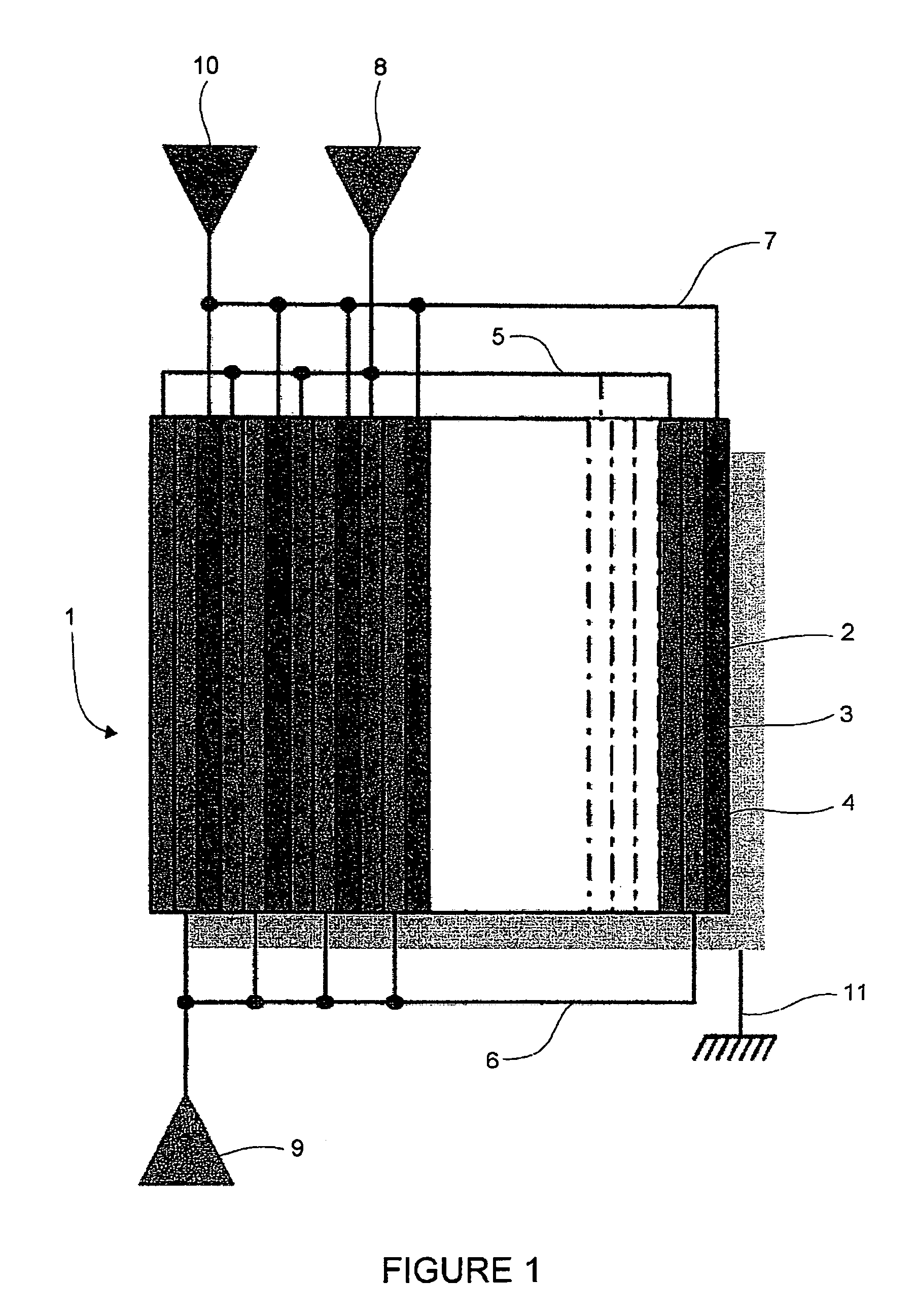
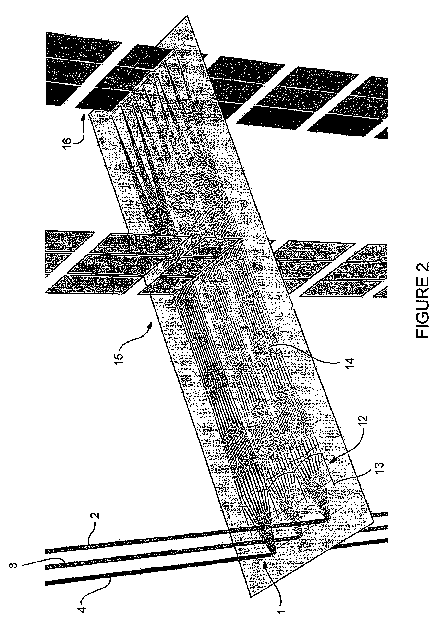
[0047]The backlighting unit 1 using organic light-emitting diodes (OLED) is a substantially plane and square or rectangular structure formed from layers of materials designed to generate light by the action of an electric current. The manufacture of such a unit can use traditional fabrication techniques for OLEDs. By way of example, an OLED can comprise a substrate onto which a first electrode is deposited, above which is a layer of organic light-emitting material which itself is covered by a second electrode layer. Sub-layers can be incorporated into the layer of organic light-emitting material in order to promote the electro-photonic conversion. Depending on fabrication modes, the OLED emission can take place from the rear (through the substrate) or from the front (through the second electrode). In addition, depending on the kind of the electrodes, anode or cathode, the anode can be at the front or vice versa. The electrodes that must be transparent to the light produced by the OLED, conventionally the anodes, are generally thin films of indium-tin oxide (ITO) whose electrical characteristics can be improved, in particular reduction of the sheet resistance, by deposition of chrome.
[0048]The backlighting unit of the invention such as can be seen schematically in FIG. 1, of the frontal emission type and with rear common cathode, however has a special configuration, namely a regular periodic repetition of an elementary pattern of three adjacent illuminating lines of OLEDs that are parallel to each other, each one being of a base colour, red 2, green 3 and blue 4, on the substantially microscopically plane surface of the unit. Each of the base colour lines of an elementary pattern has its own electrode at least on one face of the unit, here a frontal anode forming the line electrode, the other face of the unit having an electrode that is common to all the illuminating lines, here a rear common cathode 11.
[0049]The electrodes, here frontal anodes, of the various lines of the same base colour, called line electrodes, are joined together along one end of the unit 1, for red at the link 5, for green at the link 6 and for blue at the link 7. Each of the links is connected to a colour control connection or connector pin (for the base colour being considered), respectively 8, 9 and 10, that is designed to be connected to external electronic illumination control circuits not shown. All of the OLED lines of the same base colour can thus be turned on. In a preferred manner for the implementation of the backlighting unit, the entirety of the OLED lines, in other words the three base colours together, can also be simultaneously turned on. It will be noted that, given that there are three base colours and therefore three links 5, 6, 7, the said links have been distributed at either end of the illuminating lines, one at one end and two at the other end. Such an arrangement simplifies the fabrication of the links since only one insulating layer is required between the two links as compared to an arrangement where the three links would be on the same side.
[0050]In one variant, three links can be formed at both ends with their respective connections/connector pins in order to reduce the resistance of the circuits, to power the electrodes at both ends of the lines and to have an improved uniformity of the luminous emission. Indeed, the electrodes must be thin in order to transmit the light generated in the OLEDs, leading to a high resistance and voltage drop along the illuminating line, which can cause a reduction in the luminous emission towards an end of the illuminating line that is not connected relative to the connected end. The device therefore comprises one pair of anode control connections per base colour, the first connection of the pair being at a first end of the illuminating lines of the corresponding base colour, and the second connection of the pair being at a second end of the illuminating lines of the corresponding base colour, the second end being opposite to the first end, the anodes of the illuminating lines of the same base colour being linked together at either end of the illuminating lines.
[0051]On the unit such as is described above, an array of elongated cylindrical lenses 12 has been disposed, one lens per illuminating line 2, 3, 4, which can be seen more clearly in FIG. 2 showing schematically the operation of a display according to the invention. The convex face of the lenses is oriented upwards, away from the illuminating lines. Each lens is designed to form, in the forward direction, a light beam of a given base colour with substantially parallel sides.
[0052]Optical separators 13 have been disposed between the lenses, along their common lateral edges (and along the edges of the backlighting unit), in order that the illumination from an illuminating line may not interfere with that from the other illuminating lines. The optical separators are preferably optical absorbers designed to absorb the light from an illuminating line that does not fall onto the elongated cylindrical lens corresponding to the line.
[0053]The effect of the elongated cylindrical lenses is now explained in relation to FIG. 2 where a backlighting unit 1 is disposed in a display behind an electro-optical switching array 15 of pixels of the liquid crystal (LCD) type. For simplicity, only three illuminating lines of one elementary pattern of three base colours, red, green and blue and the configuration of the light rays on a plane of transverse cross section have been shown. The illuminating lines 2, 3, 4, the cylindrical lenses 12 and the pixels of the LCD switching array 15 are aligned in order that a given pixel only controls a given base colour. Of all the light rays produced by the OLED illuminating lines, only those reaching the cylindrical lenses are transmitted in the form of light beams 14 with substantially parallel edges through the pixels of the LCD switching array, in the forward direction, in order to form patterns 16 (visible or otherwise, depending on the state of the control of the pixel or pixels and of the illuminating lines). Preferably, the cylindrical lenses are not mounted directly onto the rear face of the LCD switching array so as to leave an air space whose optical index allows an adequate curvature of the rays at the exit of the cylindrical lenses. In one variant whose goal is an optimum precision, the wavelength of the base colour can be taken into account for the calculation of the corresponding cylindrical lens so as to have the same optical effects for the three base colours and thus to avoid any astigmatism of the colours that could otherwise occur.
[0054]Again in relation to FIG. 2, it will be noted that the pixels of the optical switching array are aligned in columns that are parallel to the illuminating lines of the backlighting unit and that each light beam 14 of a base colour only relates to a single column of pixels of the optical switching array. Thanks to the action of the cylindrical lenses, each one being disposed over an illuminating line thus allowing a beam with substantially parallel edges to be produced through the switching array, a column of pixels can only act on its corresponding base colour produced by the corresponding line of the backlighting unit. Thus, a system equivalent to a Köhler lighting system is formed where all the light of a given base colour collected by a cylindrical lens only passes through the corresponding pixel column of the switching array and does not spill over onto the other pixel columns.
[0055]In a typical display according to the invention, the width of an illuminating line is around 12.5 micrometers for the backlighting unit and the elongated cylindrical lenses have a thickness at the maximum thickness of the lens of around 0.2 mm, a radius of curvature of −0.088395 mm and a conicity of −0.2056. The optical absorbers are configured for absorbing the lateral light rays emitted laterally by the illuminating line outside of a cone of around ±14 degrees with respect to a median emission plane of the illuminating line in the forward direction. Lastly, the switching array of the liquid crystal type has a pixel width of around 0.1 mm, the liquid crystal being held between two glass plates, each of around 0.7 mm thickness, onto which are deposited, on the opposite surface to the liquid crystal layer, polarization layers that form a crossed polarizer and analyzer. Preferably, one of the glass plates integrates an active matrix that provides a memory effect for each pixel or liquid crystal cell; for this purpose, this glass plate for example comprises, for each pixel, a region coated with amorphous silicon into which is etched a pixel circuit that is known per se and that is designed so as to obtain the memory effect.
[0056]While the cylindrical lenses and optical separators act on light rays produced in lateral directions (perpendicular) to the illuminating lines, it will be noted that, for the rays produced in directions included in the normal median plane of the illuminating line, the light produced does not need to be controlled (redirected or absorbed) and that any light up to ±90 degrees from the normal can be used.
[0057]As has already been indicated, during operation, all the illuminating lines, in other words the three base colours, are preferably turned on, while however adjusting the level of each base colour in order to form a white of the right quality (white balancing).
[0058]In one variant in which the goal is a better white uniformity over the whole surface of the backlighting unit, the surface of the unit can be divided into individually controlled regions of three base colours encompassing a certain number of adjacent elementary patterns of three base colours and with at least three connector pins per region.
[0059]It will be understood that the few exemplary embodiments presented above are purely indicative and that those skilled in the art may be able to construct other ones that would still remain within the scope of the invention. In particular, the backlighting unit may additionally comprise electronic control circuits that are integrated and that notably allow it to be controlled via a serial or parallel link. In the simplest case, the control can be analogue. In the case where electronic logic circuits (or even a microprocessor) are implemented by integration into the backlighting unit, the control could be digital (binary). Finally, in a more sophisticated version, closed-loop control means are envisaged, where one or more optical sensors measure the luminous emission of the backlighting unit in order to maintain it at a predetermined level which, if required, could be modified by external control.