Dosing pump for a liquid fuel additive

a technology of liquid fuel additive and dosing pump, which is applied in the direction of piston pump, non-fuel substance addition to fuel, charge feed system, etc., can solve the problem of typical noise of the solenoid valve used for actuation

Inactive Publication Date: 2012-02-07
PLASTIC OMNIUM ADVANCED INNOVATION & RES SA
View PDF25 Cites 4 Cited by
  • Summary
  • Abstract
  • Description
  • Claims
  • Application Information

AI Technical Summary

Benefits of technology

[0013]The variable volume pump of the invention is preferably a syringe pump, i.e. a pump in which the piston contacts a solid surface (which may be the end of the pump cylinder bore or the inner surface of the manifold) at the end of each dose cycle. By “dose cycle,” it is meant the complete sequence of operations between 2 successive inhalations of the pump. At the end of each cycle, the syringe returns to an end stop, ensuring high repeatability. Besides, the volume of additive left in the pump body after each cycle is minimized, which in turn minimizes the potential risk of leaks of gas or vapor from the additive that may occur during temperature changes.
[0031]The materials of which the pump according to the invention are made of are chosen to be resistant to the additive to be dosed. Generally, the piston and cylinder are plastic (like PBT (polybutylene) for instance) and the seal(s) are elastomeric, most preferably a fluorinated silicone elastomer. In the case of a dish seal, its shape and material are very important to prevent stretching of the seal when the pump ‘inhales’. The profile of the seal is preferably designed so that the forces (and hence, the stretching of the seal) are minimized during inhalation. Other means may include material reinforcement of the seal or coating the seal with a material like PTFE (polytetrafluoroethylene, commonly called “Teflon”) to prevent stretch (and increase material compatibility).

Problems solved by technology

The disadvantages are:that any error associated with the piston volume is accumulated over the number of strokes, while an accurate dose is required for optimal results;possible overdosing (because of the incapacity of delivering fractions of the cylinder volume), which is expensive considering the price of the additive; andthat the solenoid valves used for the actuation are typically noisy.

Method used


Image

  • Dosing pump for a liquid fuel additive
  • Dosing pump for a liquid fuel additive
  • Dosing pump for a liquid fuel additive

Examples


embodiment 1

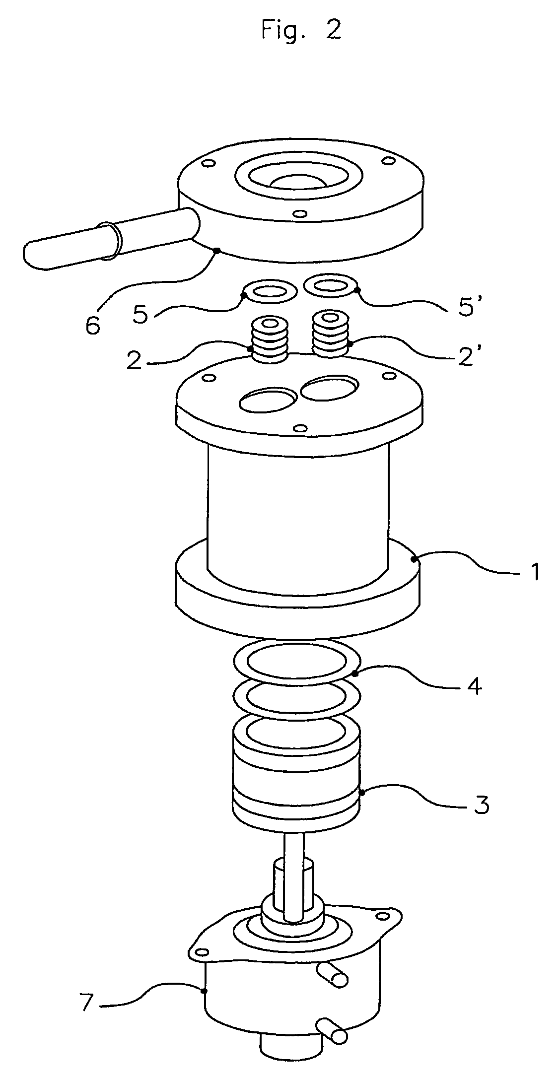
[0048]These figures represent a syringe pump with sliding seal having a capacity of about 8 ml.

[0049]The syringe inhales through an in-hole (I) in manifold (6), seal (5) and one-way valve (2), the additive liquid, by the piston (3) performing only a single proportional course at a calculated dosing quantity.

[0050]The piston (3) moves by means of a stepper motor and gear reduction which are part of an actuator (7). There is a sliding seal (4) between the piston (3) and the cylinder (1).

[0051]After the liquid inhalation, the syringe pushes through an out-hole (0) in support (6), seal (5′) and one-way valve (2′), the additive liquid, by the piston (3), to the diesel fuel tank.

DESCRIPTION OF FIGS. 3 AND 4

embodiment 2

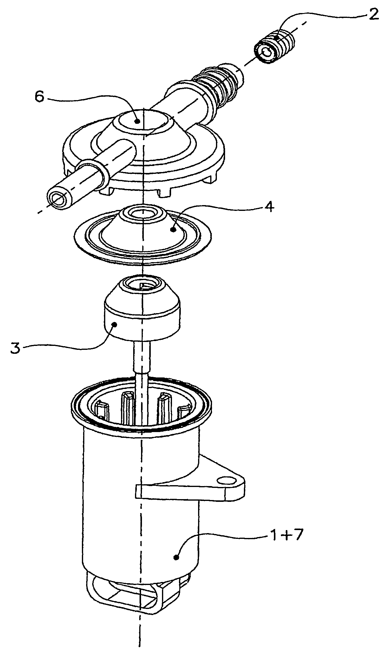
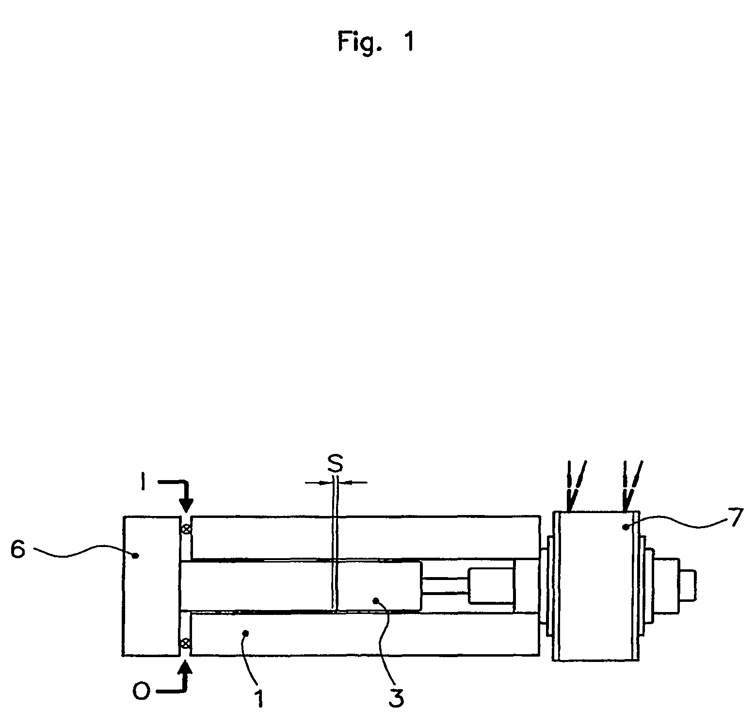
[0052]These figures represent a membrane-syringe pump with dish seal having a capacity of about 0.5 ml.

[0053]Its storage / reset position is shown in FIG. 3. The piston pushes the seal (4) up against the manifold (6), i.e. its end-stop.

[0054]The seal (4) is fixed between the cylinder (1) and manifold (6) at its perimeter (forming an additive tight seal) and attached to the piston (3) via its flat top (F). When the piston (3) moves, the top of the seal (F) moves with it and a void is created between the manifold (6) and the seal (4).

[0055]The syringe inhales through an in-hole in manifold (6) and one-way valve (2), the additive liquid, by the piston (3) performing a multiple of strokes up to the calculated dosing quantity.

[0056]The piston (3) moves by means of a stepper motor and gear reduction which are part of an actuator (7), which in this case is made in one piece with the cylinder (1).

[0057]The following sequence defines one cycle of the pump:[0058]The stepper motor is driven by t...


PUM


Abstract

A dosing pump for a liquid additive in fuel of a heavy fuel engine includes a piston, a cylinder, and a high resolution linear actuator, including a motor driven by a controller, for moving the piston axially in the cylinder. The pump includes a manifold, and a low friction dish-shaped seal having a peripheral portion forming a seal between the cylinder and the manifold in a fully extended position of the piston. The dish-shaped seal includes a top portion attached to the piston that moves with the piston such that the top portion of the seal is compressed against the manifold in the fully extended position. The shape of the seal minimizes non-linearity of the volume dosed as a function of movement of the piston, and the controller drives the motor so as to remove a remaining non-linearity of the volume dosed as a function of movement of the piston.

Description

TECHNICAL FIELD[0001]The invention concerns a dosing pump for a liquid additive (possibly very concentrated) either in the engine of a vehicle; in the exhaust gases of said engine; or in the case of an engine using a heavy fuel (i.e. fuel having more than 9 carbon atoms; typically diesel), directly in said fuel and preferably, in the fuel tank.[0002]The aim of additives like urea, liquid ammonia, and carbamates is to lower the emission of pollutants like NOx and CO by the engine, while metallic salts (like salts of iron (Fe) or cerium (Ce) in solution in a hydrocarbon solvent) are generally used in order to lower the combustion temperature of the particles retained on the filter of the exhaust system of heavy fuel engines.BACKGROUND ART[0003]Existing systems use a conventional piston pump to dose additive liquid where it has to be injected (mostly in the engine, the exhaust gases, the fuel tank, the fuel feed pipe or the fuel return pipe of said engine; this will generally be called...

Claims


Application Information

Patent Timeline
Patent Type & Authority Patents(United States)
IPC IPC(8): F04B17/00F02M25/00F04B13/00F04B17/03
CPCF02M25/00F04B13/00F04B17/03
Inventor WRENCH, NATHANLEWIS, HELEN VICTORIANAYLOR, SIMON JAMESJOHNSTONE, CHARLES DOUGLASNEAVE, JAMES BEECHING
Owner PLASTIC OMNIUM ADVANCED INNOVATION & RES SA
Why Eureka
Try Eureka