Force sensor

a technology of force sensor and sensor, which is applied in the direction of force measurement using piezo-resistive materials, instruments, force measurement apparatus, etc., can solve the problems of deteriorating detection accuracy, poor adhesion, and damage to the force sensor chip, so as to facilitate the positioning of glass members and prevent the reduction of joint strength

Active Publication Date: 2012-02-14
HONDA MOTOR CO LTD
View PDF46 Cites 32 Cited by
  • Summary
  • Abstract
  • Description
  • Claims
  • Application Information

AI Technical Summary

Benefits of technology

[0026]In the invention according to [1], the joint member is provided that joins the first glass member and the second glass member together as a single member. Therefore, two glass members can be handled as the single glass member and the number of parts can be reduced. As a result, a single positioning of the first glass member, the second glass member or the joint member results in the positioning of both the first glass member and the second glass member, which facilitates the positioning. In addition, since the first glass member and the second glass member can be handled as a single part during a joining operation, joining is facilitated.
[0052]Second, in the force sensor and the method for producing the same according to the present invention, joint strength can be prevented from being reduced in a case where the force sensor chip and the attenuator are joined through the glass member by anodic bonding.

Problems solved by technology

If the applied external force is directly transmitted to the strain resistive element, and the external force is excessively large, the force sensor chip may be damaged.
In this case, if the force sensor chip formed on the semiconductor substrate is directly joined with the attenuator made of a metal member, there arise problems, such as electric hazard including leakage from an electric source, detachment of two members at the joint portion due to a difference in coefficient of thermal expansion between two members, and thermal strain, all of which may deteriorate the detection accuracy.
However, when an epoxy resin adhesive is used at a joint portion of the attenuator and the force sensor chip, adhesion may become poor due to aged deterioration of the adhesive.
In addition, a joint surface may be deformed or adhesive strength may become smaller, due to repeated compression and tension caused by external force on the attenuator.
As a result, there arises a problem that minute change in external force cannot be accurately transmitted.
Especially, an action portion facing a center portion of the force sensor chip should be accurately positioned, though the subject to be positioned (the joint portion and the glass plate) are very small and thus the positioning frequently becomes difficult.
As a result, fracture in the joint interface may occur from alkali ion (e.g., Na+) in the glass plate 100, leading to problems, such as reduced joint strength and detachment of the joint face.
Because of this reverse voltage, reduction of joint strength, detachment of the joint surface and the like may occur at the joint portion 510, which in turn may cause deterioration in sensor accuracy.

Method used


Image

  • Force sensor
  • Force sensor
  • Force sensor

Examples


first embodiment

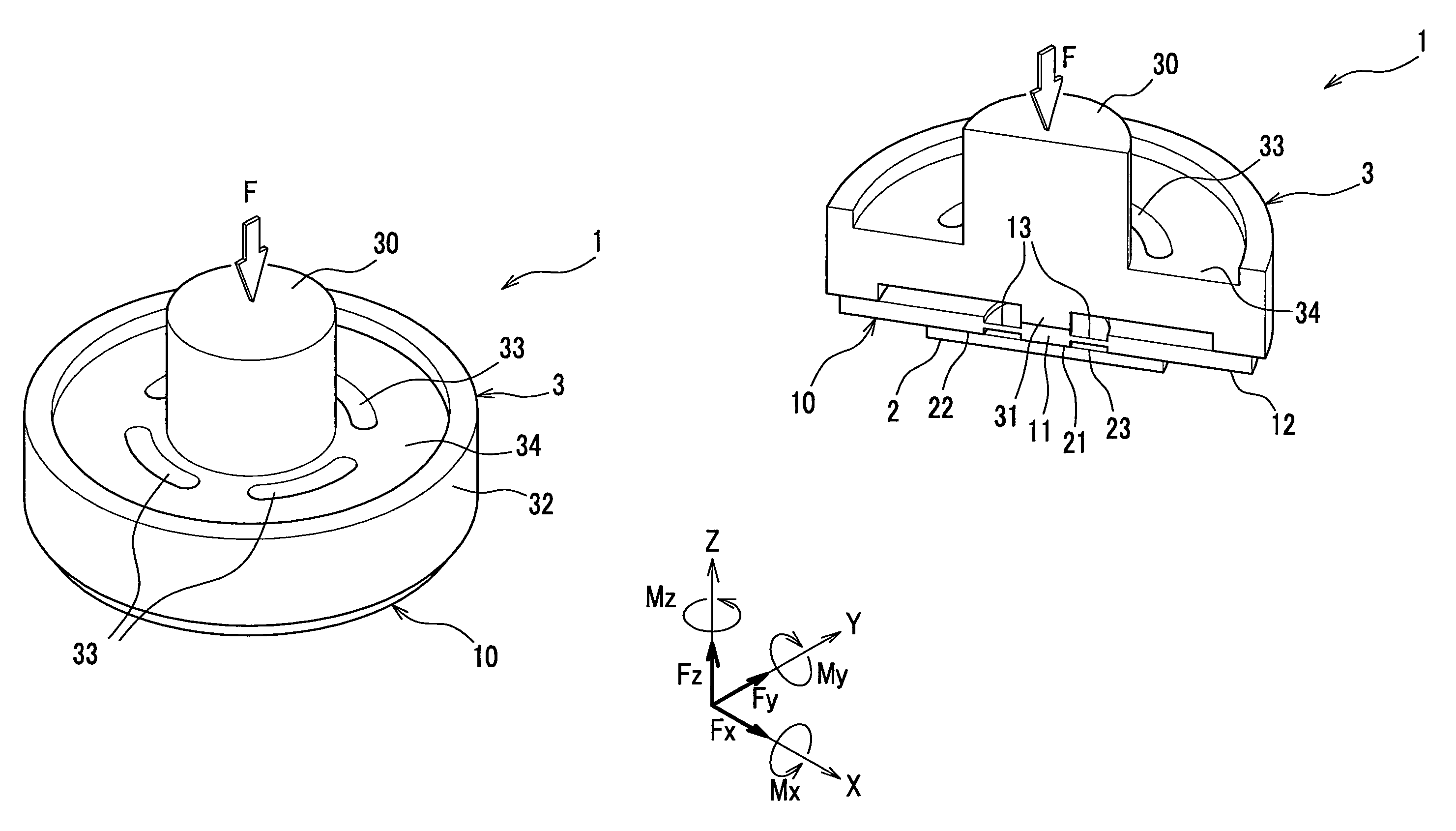
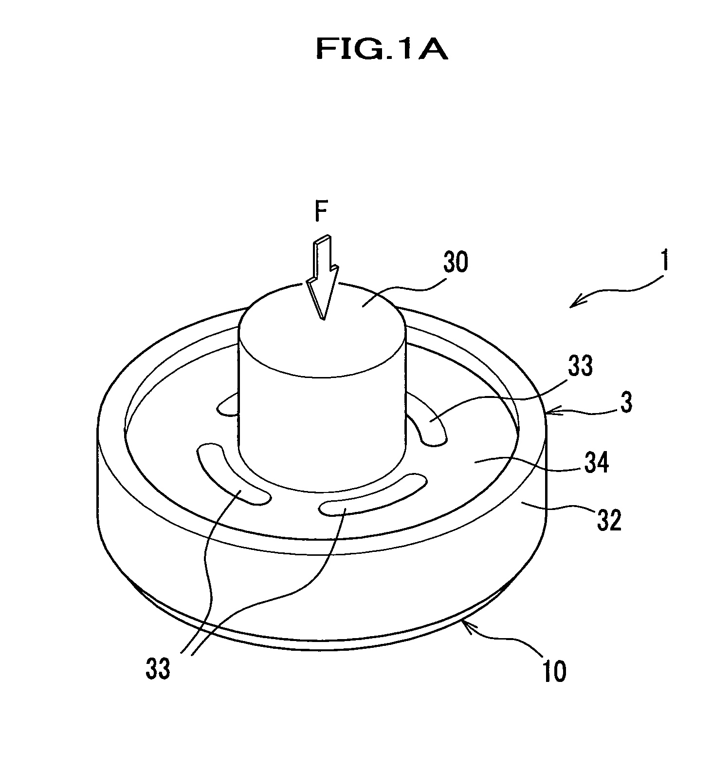
[0073]An entire framework of a force sensor according to the present invention will be describer in detail with reference to FIGS. 1-3.

[0074]It should be noted that in the drawings to be referred, for the purpose of convenience in explanation, an attenuator, a glass beam and the like are simplified, and configurations and positional relationships may be schematically and conceptually expressed. In addition, in the drawings, degree of strain and the like may be exaggeratingly expressed.

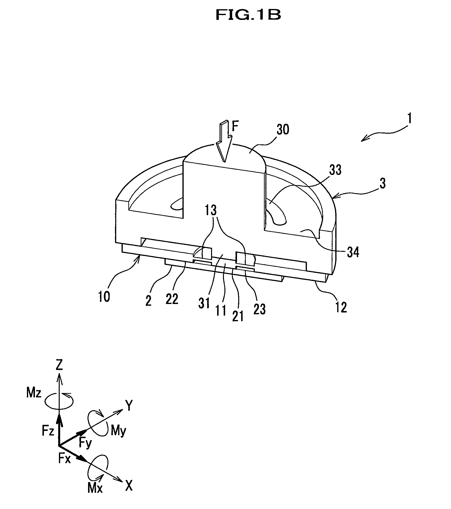
[0075]A force sensor 1 according to the present invention is configured in a shape of a circular plate with an input portion 30 protruding therefrom (see FIG. 1A), and includes a force sensor chip 2 for detecting hexaxial components of a transmitted external force F (see FIG. 1B) and an attenuator 3 for fixing the force sensor chip 2, attenuating the external force F and transmitting the attenuated external force F to the force sensor chip 2. The force sensor chip 2 and the attenuator 3 are joined thro...

second embodiment

[0156]In the glass member according to the present invention, as shown in FIGS. 15A and 15B, in each of four glass beams 13′, there is formed a discontinuous portion 19 that blocks the transmission of the external force F between the first glass member 11 and the second glass member 12. The discontinuous portion 19 is formed by cutting a middle portion of the glass beam 13′ with laser beam (by laser beam cutting).

[0157]Specifically, the discontinuous portions 19 can be formed through the buffer holes 33 (see FIG. 1) of the attenuator 3, or as shown in FIG. 16, first by forming small holes 19a in the disc portion for a laser beam cutting operation, and cutting the glass beams 13′.

[0158]It should be noted that the technique of forming the discontinuous portion 19 is not limited to the laser beam cutting, and it may be formed by mechanically cutting with a cutter or by breaking the glass beam 13′ with a load applied to the glass beam 13′. Also in these cases, the buffer holes 33 of the...


PUM

PropertyMeasurementUnit
external forceaaaaaaaaaa
joint strengthaaaaaaaaaa
sizeaaaaaaaaaa

Abstract

A force sensor 1 includes: a force sensor chip 2 including an action portion 21, a connecting portion 23 on which strain resistive elements are disposed, and a support portion 22 for supporting the action portion 21 and the connecting portion 23; an attenuator 3 including an input portion 30 to which an external force is input, a fixing portion 32 for fixing the force sensor chip 2, and a transmission portion 31 for attenuating the external force and transmitting the attenuated external force to the action portion 21; a first glass member 11 disposed between the action portion 21 and the transmission portion 31 and a second glass member 12 disposed between the support portion 22 and the fixing portion 32, through which glass members 11, 12 the force sensor chip 2 and the attenuator 3 are joined. A single or more glass beams 13 joins the first glass member 11 and the second glass member 12 together as a single member.

Description

BACKGROUND OF THE INVENTION[0001]1. Field of the Invention[0002]The present invention relates to a force sensor and a method for producing the force sensor, and particularly to a force sensor in which a positioning of a glass member is facilitated upon joining a force sensor chip and an attenuator through the glass member, and joint strength is prevented from being reduced when the force sensor chip and the attenuator are joined by anodic bonding, and a method for producing the force sensor.[0003]2. Description of the Related Art[0004]Conventionally, in an industrial robot and the like, there has been adopted a multi-axis force sensor for accurately measuring a size and direction of an external force applied to the robot during an action of the robot, in order to implement a control under which the robot appropriately and flexibly responds to the external force.[0005]As the multi-axis force sensor, for example, there has been known a force sensor utilizing a property of a strain res...

Claims


Application Information

Patent Timeline
Patent Type & Authority Patents(United States)
IPC IPC(8): G01L1/22G01D7/00H01C17/28H01C17/00
CPCG01L1/18G01L1/2231G01L5/162Y10T29/49082Y10T29/49103Y10T29/49002
Inventor OHSATO, TAKESHIYASUIE, SHIGENORIHIRABAYASHI, YUSUKEYOKOBAYASHI, HIROSHI
Owner HONDA MOTOR CO LTD
Why Eureka
Try Eureka