Film formation method and method for manufacturing light-emitting device
a technology of film formation and manufacturing method, which is applied in the direction of solid-state devices, solid-state diffusion coatings, chemical vapor deposition coatings, etc., can solve the problems of reducing manufacturing efficiency, reducing the time required for evacuation of film formation chambers, and reducing the utilization efficiency of materials, so as to reduce the distance between an evaporation source and a substrate on which a film is formed, the interval of maintenance can be extended, and the effect of reducing the tim
- Summary
- Abstract
- Description
- Claims
- Application Information
AI Technical Summary
Benefits of technology
Problems solved by technology
Method used
Image
Examples
embodiment mode 1
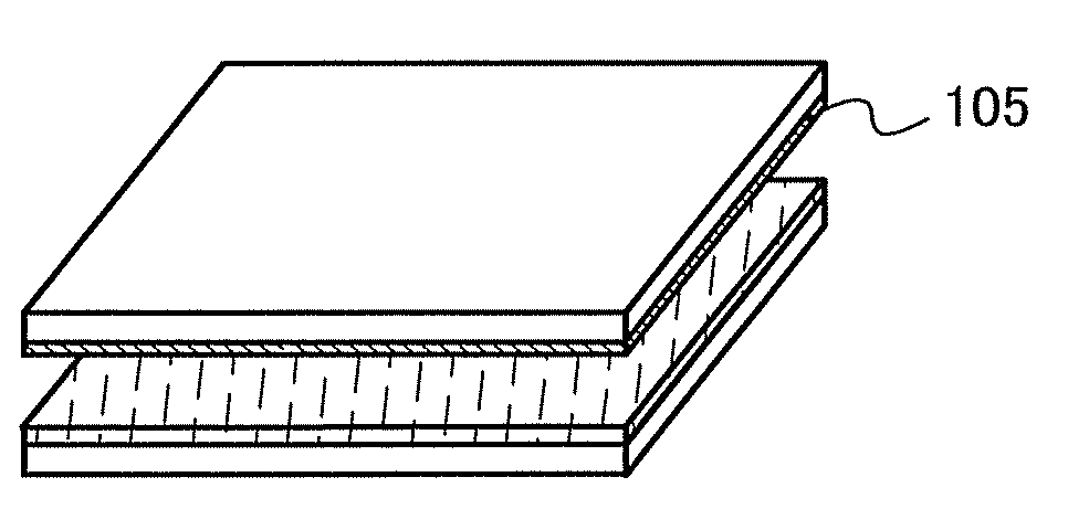
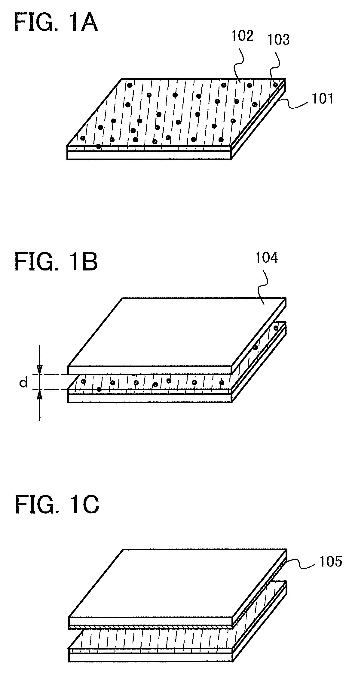
[0066]One mode of a film formation method of the present invention is described with reference to the drawings. FIGS. 1A to 1C are perspective views showing a concept of a film formation method of this embodiment mode.
[0067]First, a first material layer 102 including an evaporation material 103 is formed over a main surface of a first substrate 101 (see FIG. 1A). Here, the first substrate 101 is an evaporation source substrate, and the first material layer 102 is a layer including a mixture of the evaporation material 103 and a binder material. The binder material is a substance of higher molecular weight than the evaporation material 103.
[0068]Next, a second substrate 104 is placed so as to face the first substrate 101 (see FIG. 1B). Here, the second substrate 104 is a substrate on which a film is formed. The second substrate 104 is placed to face the first material layer 102 formed over the first substrate 101. A surface of the first material layer 102 and a surface of the second ...
embodiment mode 2
[0110]This embodiment mode describes an example of a mode of the present invention, which is different from Embodiment Mode 1, with reference to the drawings. In specific, the case is described where a mixture layer is selectively formed over an evaporation source substrate.
[0111]FIGS. 5A to 5C show an example of the case where a mixture layer is selectively formed. Here, a first material layer 202 which is a mixture layer is formed over a first substrate 201 which is an evaporation source substrate by an ink-jet method. First, a mixture layer of an evaporation material 203 and a material of higher molecular weight than the evaporation material 203 is discharged from a head 200, whereby the first material layer 202 is selectively formed over a main surface of the first substrate 201 (see FIG. 5A). Here, the first substrate 201 serves as an evaporation source substrate.
[0112]Next, a second substrate 204 is placed so as to face the first substrate 201 (see FIG. 5B). Here, the second s...
embodiment mode 3
[0117]This embodiment mode describes an example of a mode of the present invention, which is different from Embodiment Mode 1, with reference to the drawings. In specific, the case is described where a thermally conductive layer is selectively formed over an evaporation source substrate and a binder material layer is formed over the evaporation source substrate and the thermally conductive layer.
[0118]FIGS. 6A to 6D show an example of the case where a thermally conductive layer is selectively formed. Here, a thermally conductive layer 302 is formed over the first substrate 301 by an ink-jet method. First, a material which forms the thermally conductive layer 302 is discharged from a head 300 to selectively form the thermally conductive layer 302 over a main surface of the first substrate 301 (see FIG. 6A). Here, the first substrate 301 serves as an evaporation source substrate.
[0119]The thermally conductive layer is not particularly limited as long as it is formed from a material wi...
PUM
| Property | Measurement | Unit |
|---|---|---|
| distance | aaaaa | aaaaa |
| sublimation temperature | aaaaa | aaaaa |
| size | aaaaa | aaaaa |
Abstract
Description
Claims
Application Information
 - R&D
- Intellectual Property
- Life Sciences
- Materials
- Tech Scout
- Unparalleled Data Quality
- Higher Quality Content
- 60% Fewer Hallucinations
Browse by: Latest US Patents, China's latest patents, Technical Efficacy Thesaurus, Application Domain, Technology Topic, Popular Technical Reports.
© 2025 PatSnap. All rights reserved.Legal|Privacy policy|Modern Slavery Act Transparency Statement|Sitemap|About US| Contact US: help@patsnap.com


