Embedded scribe lane crack arrest structure for improved IC package reliability of plastic flip chip devices

a crack arrest structure and flip chip technology, applied in semiconductor devices, semiconductor/solid-state device details, electrical devices, etc., can solve the problems of massive cracks in the scribe lanes that can migrate towards the die seal, cracks in the die seal, and high collateral damage of the die, so as to reduce the damage of the wafer from dicing and minimize crack damage

Active Publication Date: 2012-02-28
TEXAS INSTR INC
View PDF6 Cites 13 Cited by
  • Summary
  • Abstract
  • Description
  • Claims
  • Application Information

AI Technical Summary

Benefits of technology

[0006]Another embodiment is directed to a method of decreasing damage from wafer dicing. The method includes providing a wafer with adjacent die formed thereon. The method also includes providing scribe lanes located between the adjacent die and forming a crack arrest structure between the scribe lanes.
[0007]Another embodiment is directed to an apparatus for minimizing crack damage from wafer dicing. The apparatus includes a wafer with a plurality of die and at least one scribe lane disposed thereon, wherein the at least one scribe lane is located between the plurality of die. The apparatus also includes a crack arrest structure located within the at least one scribe lane.

Problems solved by technology

A problem exists in known wafer dicing methods, however, when chipping or cracking of the die edge occurs during the dicing cut, particularly when dicing through brittle, low-k dielectrics.
Although most dies incorporate die seals that help protect the edges of the dies, the dies are still highly susceptible to collateral damage from the dicing operation.
In particular, cracks resulting from the dicing process can propagate significant distances from the saw line, and moisture from water exposure or intentional acceleration resulting from exposing packages to humid environments can lead to massive cracks in the scribe lanes that can migrate towards the die seal.
In certain cases, such a crack can rupture the die seal and curtail the lifetime of the die.

Method used


Image

  • Embedded scribe lane crack arrest structure for improved IC package reliability of plastic flip chip devices
  • Embedded scribe lane crack arrest structure for improved IC package reliability of plastic flip chip devices
  • Embedded scribe lane crack arrest structure for improved IC package reliability of plastic flip chip devices

Examples


Embodiment Construction

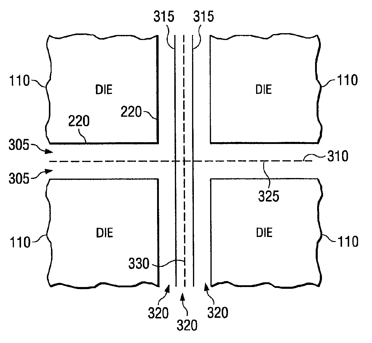
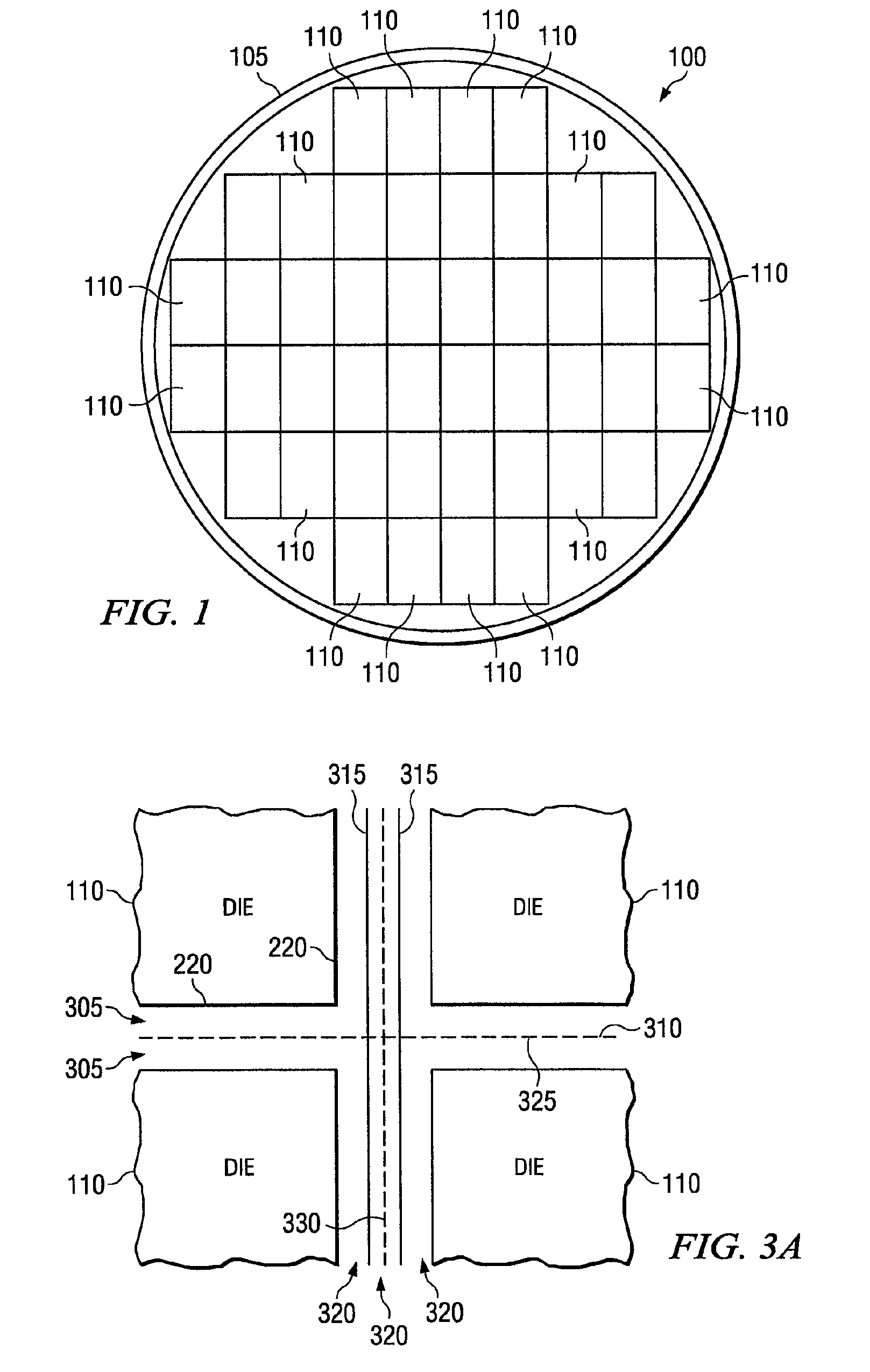
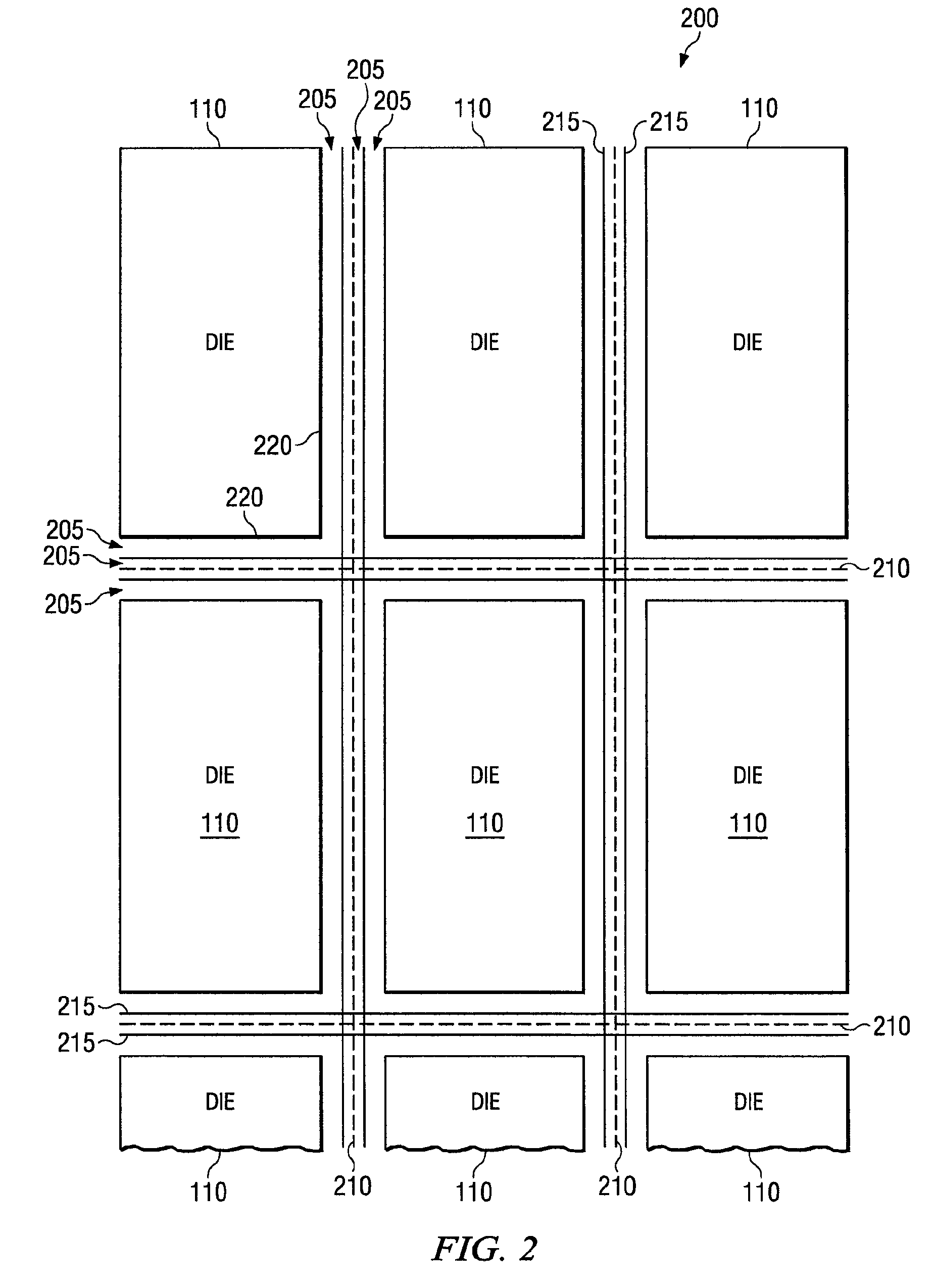
[0014]Embodiments of the present disclosure are directed towards a system, method, and apparatus for suppressing cracks during the wafer dicing process. The crack suppression technology reduces damage to the wafer die and allows for improved package reliability. The system can be implemented on new or existing wafer designs, which minimizes both manufacturing and redesign costs.

[0015]The crack suppression system utilizes crack arrest structures (CAS) to reduce the formation and acceleration of cracks resulting from the wafer dicing operation. Further, the CAS provides a moisture diffusion block to prevent moisture from entering the dielectrics between the CAS and the die, thereby preventing an increase in crack propagation rates toward the die. The wafer initially contains a plurality of die that need to be separated from each other. The plurality of die each contain a die seal around the border of the die for an initial layer of protection against cracks, moisture, and other damage...


PUM


Abstract

A system, method, and apparatus for suppressing cracks in the wafer dicing process. A wafer includes a plurality of die attached to a frame and mounting tape, with the die separated by a plurality of scribe lanes. An existing die seal generally protects the boundary of the die but can still fail to fully protect the die from excessive cracks induced by dicing damage, particularly when dicing through brittle, low-k dielectrics. The system, method, and apparatus includes embedding a crack arrest structure (CAS) between adjacent scribe lanes. Upon a mechanical saw dicing the wafer, the CAS creates a moisture diffusion block, and can absorb or significantly diminish the energy of cracks propagating towards the individual die seals. Furthermore, the system, method, and apparatus can be implemented without the need to increase the width of the scribe lanes.

Description

FIELD OF THE INVENTION[0001]This invention generally relates to semiconductor wafers having embedded crack arrest structures (CAS) to suppress damage resulting from the wafer dicing process.BACKGROUND OF THE INVENTION[0002]A wafer is a thin slice of semiconductor material often containing a plurality of microdevices, or dies. Dies are fabricated on the wafer, which is suspended within a supporting frame via mounting tape. A sawing or dicing process is performed on the wafer to separate the individual dies from each other. The mounting tape continues to hold the dies after the dicing process until the separated dies are removed from the mounting tape. Once fully removed, the dies are packaged and put into end-user electronic devices, usually as integrated circuits to provide electronic functionality to the devices.[0003]The wafer surface is designed so that the individual dies are separated by a plurality of scribe lanes. A physical cutting tool such as a saw uses the scribe lanes as...

Claims


Application Information

Patent Timeline
Patent Type & Authority Patents(United States)
IPC IPC(8): H01L23/544
CPCH01L21/78H01L23/562H01L23/585H01L2924/0002H01L2924/00
Inventor WEST, JEFFREY A.VINCENT, PATRICIA DIANETUERCK, ROBERT A.
Owner TEXAS INSTR INC
Why Eureka
Try Eureka