Secondary battery of improved high-rate discharging properties
a technology of high-rate discharge and secondary batteries, which is applied in the direction of non-aqueous electrolyte cells, cell components, electrochemical generators, etc., can solve the problems of deteriorating rate properties of secondary batteries, failure to achieve easy wetting of electrode materials, and high viscosity and surface tension of electrolyte, so as to improve the wettability of electrolyte, and reduce the effect of adverse effects on the operation mechanism o
- Summary
- Abstract
- Description
- Claims
- Application Information
AI Technical Summary
Benefits of technology
Problems solved by technology
Method used
Image
Examples
example 1
[0055]A lithium secondary battery was fabricated according to the following procedure.
[0056]1-1. Fabrication of Cathode
[0057]A mixture of LiCoO2 and LiNi1 / 3Mn1 / 3Co1 / 3O2 (“NMC”) having an average particle diameter of about 10 μm was used as a cathode active material. Specifically, 47.5% by weight of LiCoO2, 47.5% by weight of NMC, 2.5% by weight of Super-P (conductive material) and 2.5% by weight of PVdF (binder) were added to N-methyl-2-pyrrolidone (NMP) as a solvent to thereby prepare a cathode slurry. Thereafter, the resulting cathode slurry was coated at 3 mAh / cm2 on an aluminum current collector, dried and pressed to a thickness of 131 μm to thereby fabricate a cathode.
[0058]1-2. Fabrication of Anode
[0059]95.3% by weight of artificial graphite having an average particle diameter of about 10 μm as an anode active material, 0.7% by weight of Super-P (conductive material) and 4% by weight of PVdF (binder) were added to NAP as a solvent to thereby prepare an anode slurry. Thereafter...
example 2
[0067]A lithium secondary battery was fabricated in the same manner as in Example 1, except that 20% by weight of NMC was added to a cathode active material.
experimental example 1
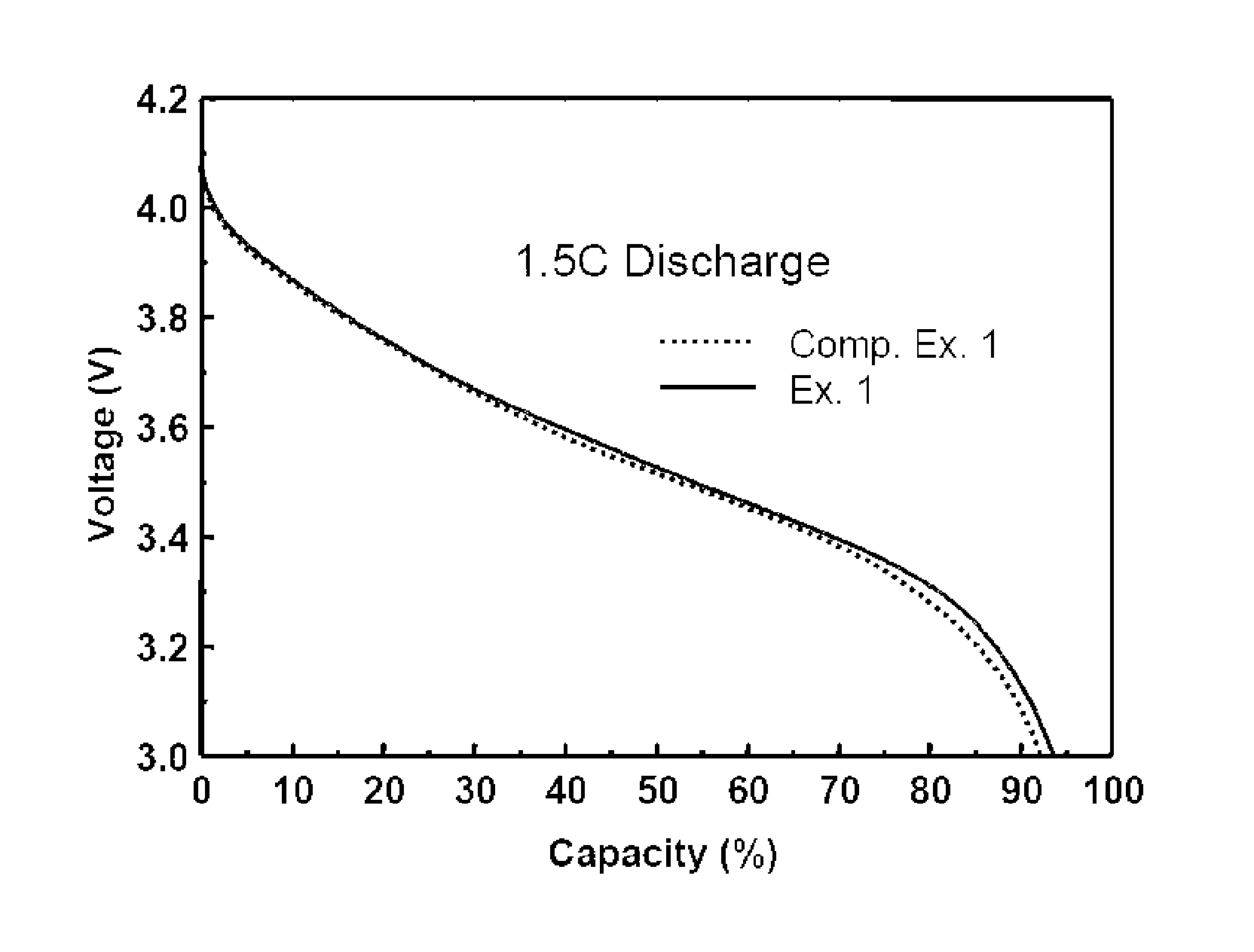
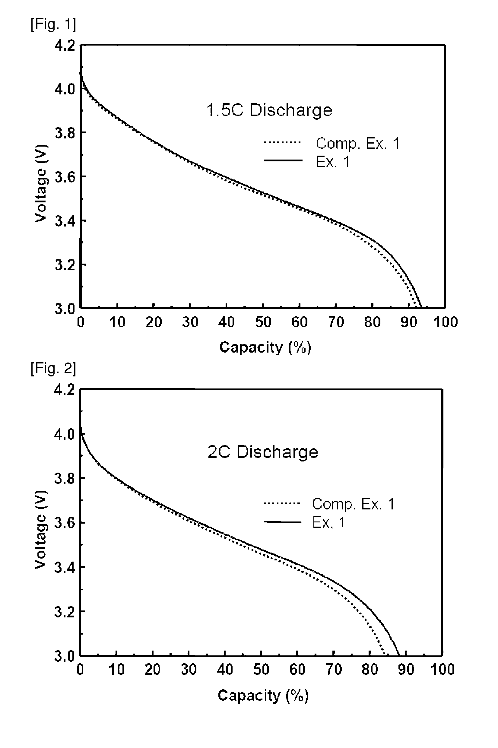
[0069]Lithium secondary batteries fabricated in Examples 1 and 2 and Comparative Examples 1 to 4 were discharged at a rate of 0.2 C, 0.5 C, 1 C, 1.5 C and 2 C, and a discharge capacity was compared therebetween. The results thus obtained are given in Table 1 below. Table 1 shows relative values of the capacity under various discharge conditions, by taking a discharge condition of 0.2 C to be a reference (100). In addition, 1.5 C and 2 C discharge graphs for secondary batteries of Example 1 and Comparative Example 1 are shown in FIGS. 1 and 2.
[0070]
TABLE 1Comp.Comp.Comp.Comp.Ex. 1Ex. 1Ex. 2Ex. 3Ex. 2Ex. 40.2 C1001001001001001000.5 C97.93497.41498.39098.32198.29098.291 1 C95.59294.61296.72196.72496.7296.551.5 C93.61192.21195.94996.00695.82194.352 2 C88.33784.28192.70992.83291.01889.201
[0071]As can be seen from Table 1, an increase in the discharge rate generally leads to a decrease in the discharge capacity. However, upon high-rate discharging at a rate of more than 1 C, the battery o...
PUM
| Property | Measurement | Unit |
|---|---|---|
| thickness | aaaaa | aaaaa |
| thickness | aaaaa | aaaaa |
| pore diameter | aaaaa | aaaaa |
Abstract
Description
Claims
Application Information
 - R&D
- Intellectual Property
- Life Sciences
- Materials
- Tech Scout
- Unparalleled Data Quality
- Higher Quality Content
- 60% Fewer Hallucinations
Browse by: Latest US Patents, China's latest patents, Technical Efficacy Thesaurus, Application Domain, Technology Topic, Popular Technical Reports.
© 2025 PatSnap. All rights reserved.Legal|Privacy policy|Modern Slavery Act Transparency Statement|Sitemap|About US| Contact US: help@patsnap.com


