

Areal modulator for intensity modulated radiation therapy
a radiation therapy and radiation modulator technology, applied in the field of radiation therapy systems, can solve the problems of slow and yet less precise approach, incongruity of dose deposited by proton beam along the entrance path of beam, and inconvenient us
- Summary
- Abstract
- Description
- Claims
- Application Information
AI Technical Summary
Benefits of technology
Problems solved by technology
Method used
Image

Examples
Embodiment Construction
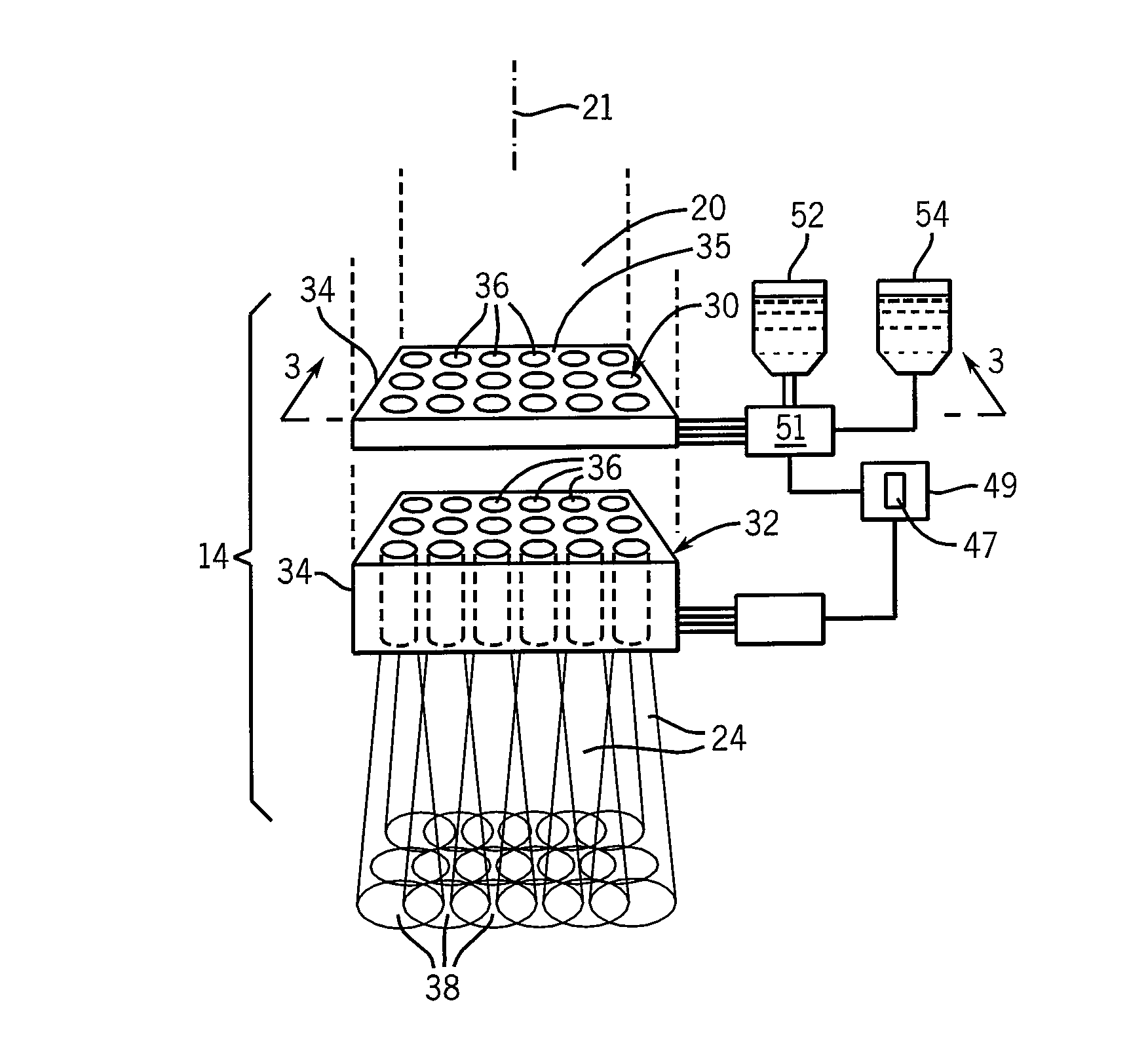
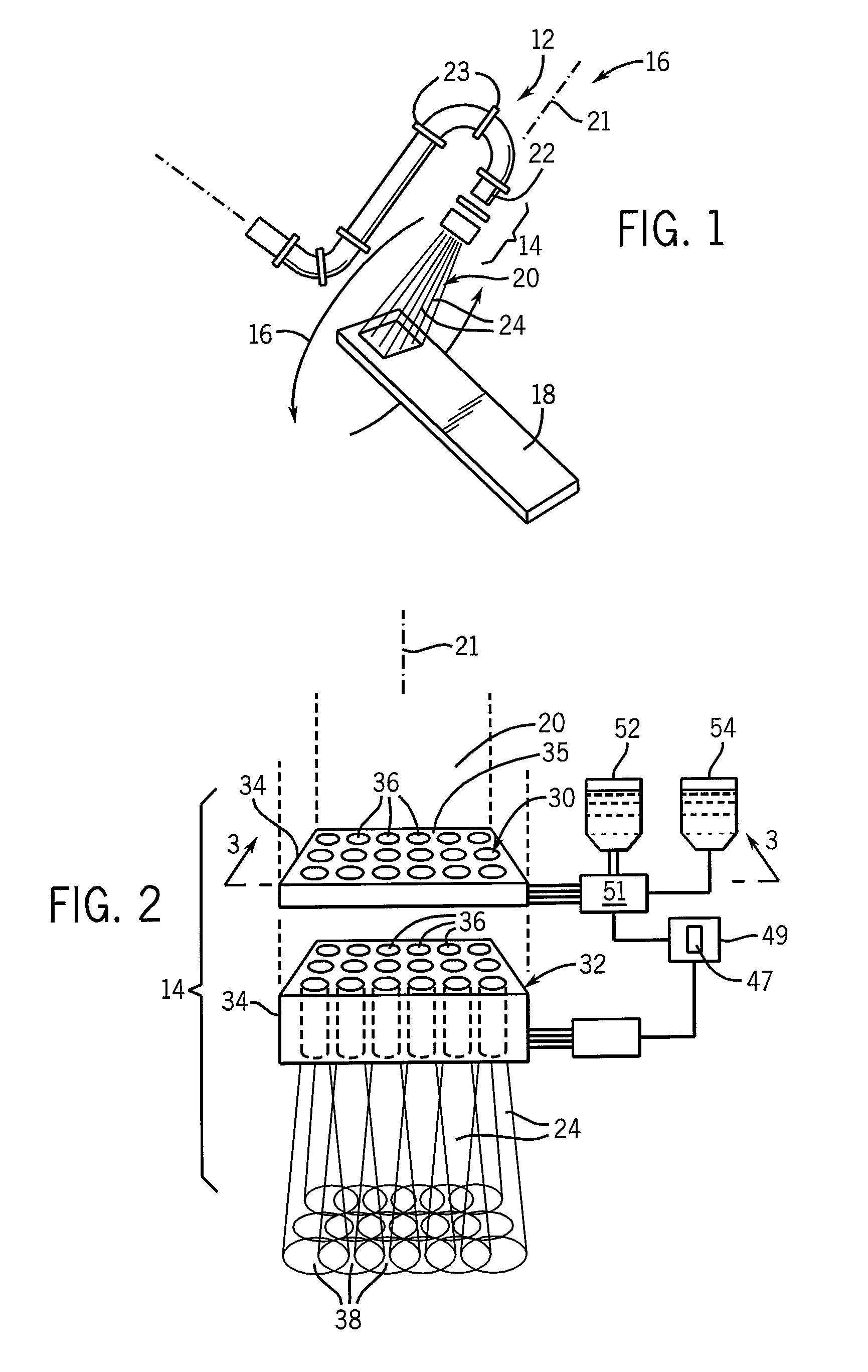
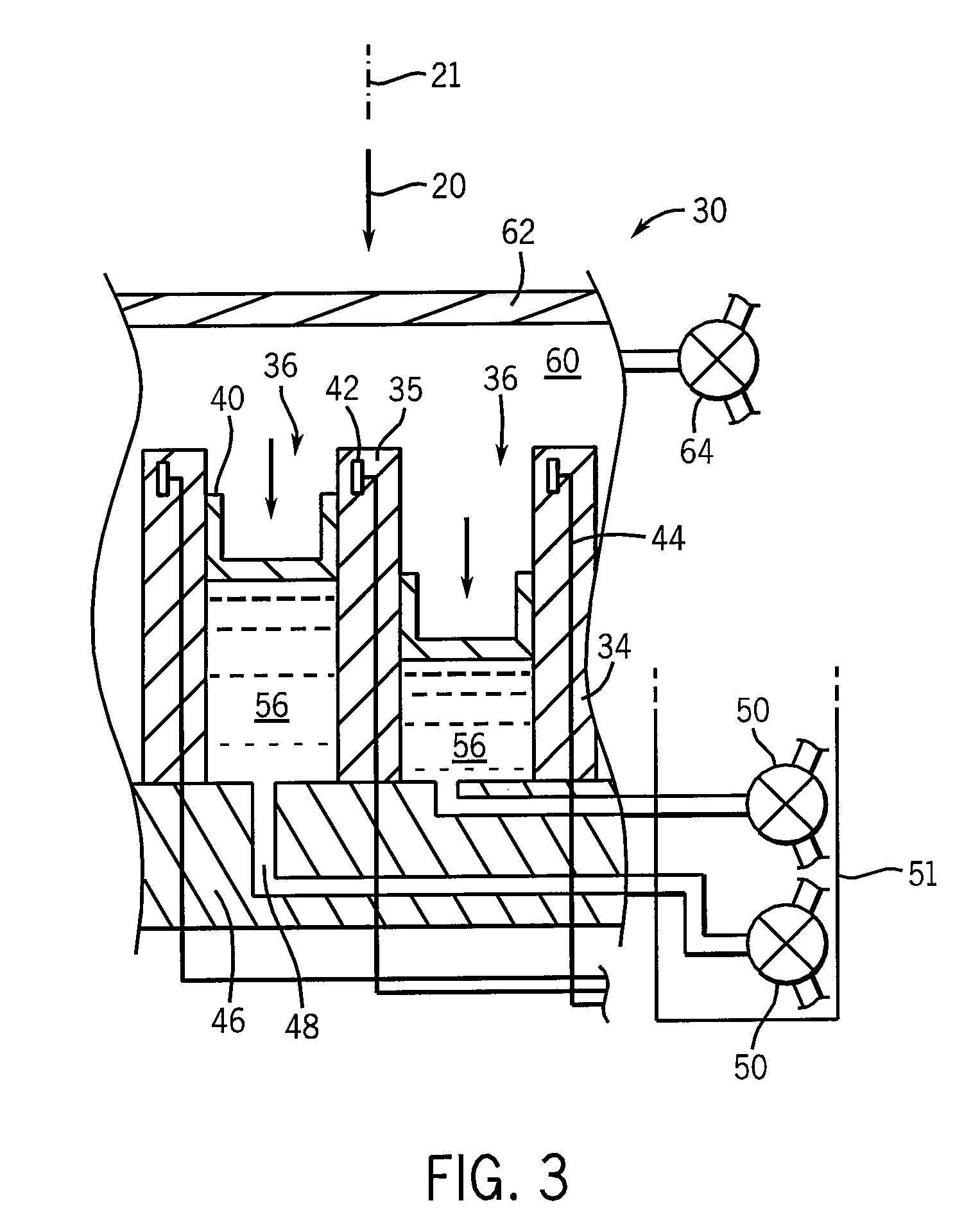
[0011]The present inventors have determined that, particularly for proton radiation, the spreading of the beam after modulation permits the significant separation of radiating modulating channels of an areal modulator without creating significant cold spots. This spacing is sufficient to permit dimensionally accurate channel walls, for example, to permit modulation by changing a height of a column of liquid capped with a piston and / or the use of more shutter systems using rotating elements that necessarily leave gaps between them. The spacing of the channels also allows actuating mechanisms and sensors to be located adjacent to the attenuation elements in the channel walls.
[0012]Specifically then, the present invention provides a radiation therapy machine having a patient support and a source of a radiation providing an area beam directed toward a patient to expose tissue of the patient supported by the patient support. An areal modulator is position between the source of radiation ...
PUM
 Abstract
Description
Claims
Application Information