Property measurement apparatus and property measurement method

a measurement apparatus and property technology, applied in the direction of fluid tightness measurement, instrumentation, fluid leakage detection, etc., can solve the problems of large noise, deterioration of precision of dynamic viscoelasticity measurement, and no longer observe the dynamic response of the sample,

Active Publication Date: 2012-03-13
SONY CORP
View PDF6 Cites 7 Cited by
  • Summary
  • Abstract
  • Description
  • Claims
  • Application Information

AI Technical Summary

Benefits of technology

[0021]In the property measurement apparatus according to the embodiment of the present invention, the impedance measurement section for measuring the impedance of a sample is provided in the second plate instead of providing the impedance measurement section in the first plate which is linked to a rotation shaft. Thus, even if a sample having a small viscosity coefficient or a sample having a large viscosity coefficient is used as a subject of measurement, both the dynamic viscoelasticity and dielectric characteristic of the sample can be measured in one measurement at the same time with a high degree of precision. A typical example of the sample having a small viscosity coefficient is a liquid whereas a typical example of the sample having a large viscosity coefficient is a gel-state substance.

Problems solved by technology

In the case of the method for measuring a dielectric characteristic of a sample by bringing the metallic clip into contact with the rotation shaft of the rotary rheometer, however, when a sample with a small viscosity coefficient is measured, frictions between the metallic clip and the rotation shaft become predominant so that the dynamic response of the sample can no longer be observed.
As a result, there is raised a problem that the precision of the measurement of the dynamic viscoelasticity deteriorates.
In addition, also in the measurement of a dielectric characteristic, the goodness and badness of electric contact with the metallic clip varies every second due to the movement of the rotation shaft, and the variations in goodness and badness become large noises.
As a result, there is raised a problem that the dielectric response of the sample cannot be evaluated correctly.
That is to say, the method of bringing a member into contact with the rotation shaft and / or the upper plate in order to assure electrical contacts with the rotation shaft and / or the upper plate undesirably introduces large errors to both the dynamic measurement and the electric measurement.
However, this method is not capable of measuring an extremely small torque by making use of an air bearing.
Thus, there is a problem that applications of this method are very limited.
In addition, since this method makes use of mercury, from the safety point of view, this method is not desirable.
Since the viscosity coefficient, the dielectric constant and the specific electric conductivity are not measured directly, however, there is a problem that the reliability of the measured value of each of the viscosity coefficient, the dielectric constant and the specific electric conductivity is poor in comparison with values obtained as results of direct measurements.
In addition, the configuration of each of the measurement apparatus described in Patent Documents 1 and 2 raises a problem that the apparatus are not capable of measuring the dynamic viscoelasticity by varying the measurement frequency.
Thus, each of the measurement apparatus described in Patent Documents 1 and 2 raises a problem that it is impossible to measure the dielectric constant and the specific electric conductivity with a high degree of precision in a high frequency range such as the range of frequencies not lower than 1 MHz in particular.
As described above, the existing measurement apparatus and the existing measurement method are not capable of measuring both the dynamic viscoelasticity and dielectric characteristic of a sample having a small viscosity coefficient in one measurement at the same time with a high degree of precision.

Method used


Image

  • Property measurement apparatus and property measurement method
  • Property measurement apparatus and property measurement method
  • Property measurement apparatus and property measurement method

Examples


first embodiment

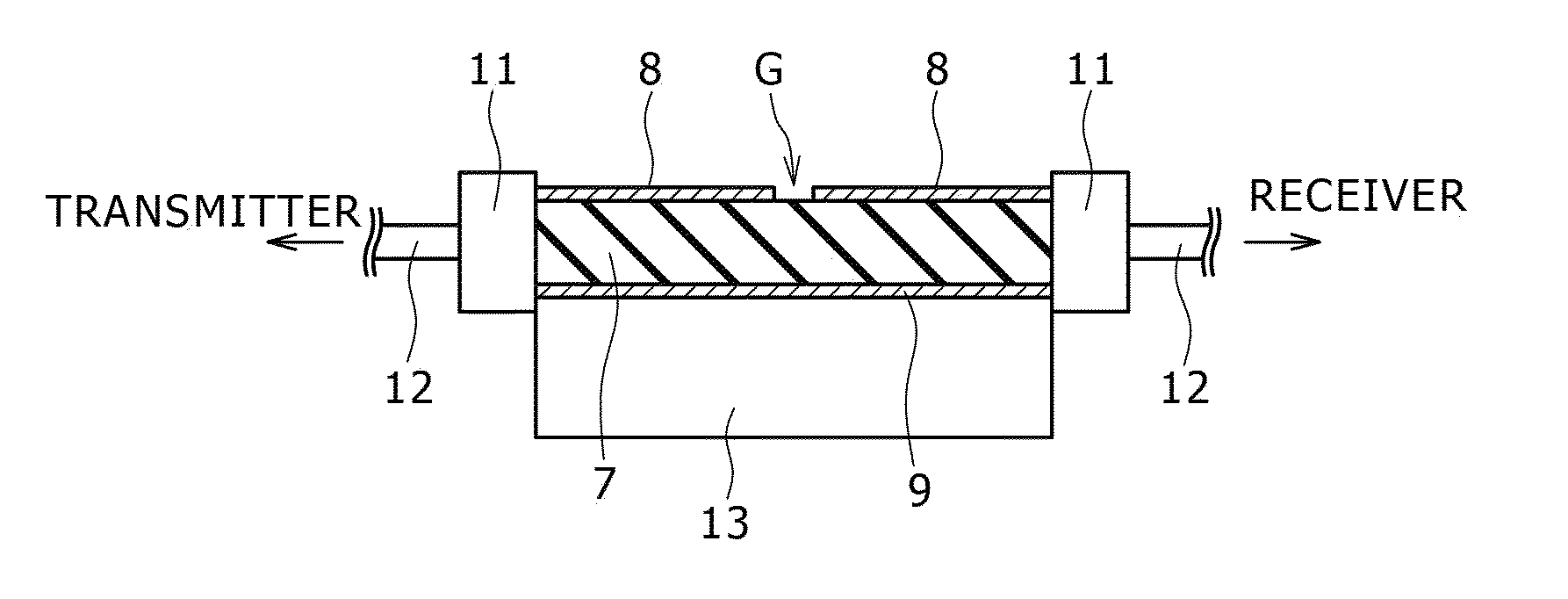
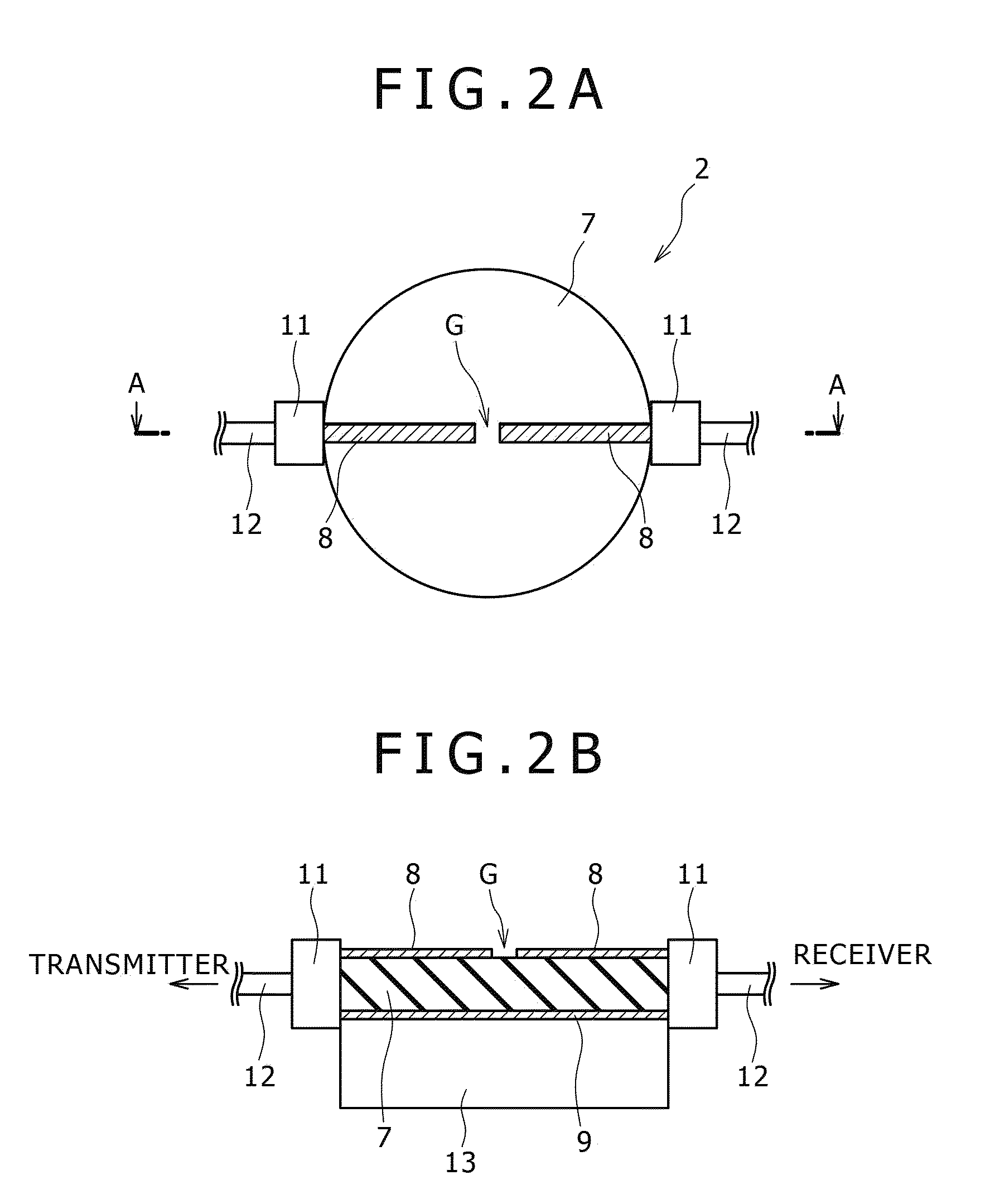
[0037]As described above, in the property measurement apparatus 10 according to the present invention, the base 7 is an insulation layer, on both surfaces of which the upper conductive layer 8 and the lower conductive layer 9 are each created to form a high-frequency transmission line. In the lower plate 2 also functioning as an impedance measurement section having the configuration described above, a sample 5 serving as the subject of measurement is introduced to the layer breaking gap G by adoption of a selected method. With the sample 5 introduced to the layer breaking gap G, an electrical signal is transmitted to the conductive layers 8 and 9. By carrying out an analysis determined in advance on the electrical signal, the impedance of the sample 5 can be measured. To be more specific, in the operation to measure the impedance of the sample 5, a transmitter applies a voltage between the conductive layers 8 and 9 whereas an electrical signal passing through the layer breaking gap ...

second embodiment

[0070]As shown in the diagram of FIG. 3, the impedance measurement section in the second plate 20 employed in the property measurement apparatus according to the present invention is a pair of comb-shaped electrodes 22a and 22b which are engaged with each other. The comb-shaped electrodes 22a and 22b which are separated away by a fixed gap from a specific surface of a base 21 which is made of an insulation material such as alumina and glass. The specific surface of the base 21 is a surface with which the sample 5 is to be brought into contact. By providing a planar electrode structure including the comb-shaped electrodes 22a and 22b engaged with each other in this way, it is possible to increase the strength of an electric field leaking out from the comb-shaped electrodes 22a and 22b to the sample 5. As a result, the sensitivity of the measurement of the impedance of the sample 5 can be improved.

[0071]The comb-shaped planar electrodes 22a and 22b can be created by carrying out a fil...


PUM

PropertyMeasurementUnit
dielectric constantaaaaaaaaaa
frequenciesaaaaaaaaaa

Abstract

Disclosed herein is a property measurement apparatus including: a first plate installed in a state of being rotatable and / or vibratable; and a second plate placed to face the first plate and provided with an impedance measurement section, wherein a stress caused by a distortion generated by rotating or vibrating the first plate to serve as a distortion given to a sample provided in a gap between the first and second plates is measured, and at the same time, the impedance measurement section measures the impedance of the sample.

Description

BACKGROUND OF THE INVENTION[0001]1. Field of the Invention[0002]In general, embodiments of the present invention relates to a property measurement apparatus for measuring a stress which is generated in a sample when a distortion is given to the sample and measuring the impedance of the sample and relates to a property measurement method to be adopted by the property measurement apparatus. More particularly, the embodiments of the present invention relates to a technology for measuring both the dynamic viscoelasticity and dielectric characteristic of a sample at the same time in one measurement.[0003]2. Description of the Related Art[0004]In the past, a rotary rheometer has been used widely for measuring dynamic viscoelasticity. In general, a rotary rheometer has a configuration in which a sample is sandwiched by a planar lower plate fixed on the rheometer apparatus and a conical or planar upper plate having an upper surface linked to a bearing by a shaft. In such a configuration, th...

Claims


Application Information

Patent Timeline
Patent Type & Authority Patents(United States)
IPC IPC(8): G01N11/14
CPCG01N11/142G01N11/165G01N2011/0066
Inventor HAYASHI, YOSHIHITO
Owner SONY CORP
Why Eureka
Try Eureka