
RF communication system

a communication system and communication channel technology, applied in the field of rf communication system, can solve the problems of complex overall configuration of each apparatus, inability to use fixed channels, and time-consuming to establish communication

Inactive Publication Date: 2012-03-13
SMK CORP
View PDF15 Cites 30 Cited by
  • Summary
  • Abstract
  • Description
  • Claims
  • Application Information

AI Technical Summary

Benefits of technology

This approach simplifies the configuration of both the transmitter and receiver, reduces the risk of reception errors, and allows for reliable remote control of appliances even in noisy environments without the need for extensive modifications to the microcontroller, ensuring timely and accurate control data transmission.

Problems solved by technology

However, because the communication environment changes, there are times when a fixed channel cannot be used.
Nevertheless, the method discussed above, wherein RF communications is established with a communication counterpart via the multiscan method, requires a procedure that demands a response signal from the communication counterpart, and is therefore unpreferable because that procedure is complicated in an RF communications system that remotely controls a controlled apparatus, such as a home appliance, with a remote control transmitter.
In addition, in order to examine the electric field intensity of all channels in the available frequency band on the transmitter side and to receive an RF signal transmitted from the transmitter on the receiver side, both the transmitter and the receiver must perform a reception scan of all channels so as to detect the RF signal, and therefore it takes time to establish communication and the overall configuration of each apparatus becomes complicated.
Furthermore, with the RF communications system that remotely controls the controlled apparatus with the remote control transmitter, the controlled apparatus should receive the RF signal transmitted from the remote control transmitter, and therefore, despite the need to set the reception channel to a channel for which the electric field intensity is low at the location of the controlled apparatus, which is on the receiver side, the abovementioned conventional art sets the common working channel to a channel for which the electric field intensity is low in the vicinity of the transmitter, which makes communication prone to reception errors at the controlled apparatus.
In particular, in contrast with the controlled apparatus, which is at a fixed position and is in a reception environment that does not change greatly, if the remote control transmitter approaches a source that generates strong electromagnetic waves, such as a microwave oven, then there are cases wherein the optimal channel for RF communications cannot be selected with the conventional method that searches for a channel with low electric field intensity at the location of the remote control transmitter.
However, in order to control a controlled apparatus that is equipped with such a microcontroller via an RF signal, it is not sufficient to just add an RF receiving circuit unit that has, for example, an antenna and a UART interface, but rather a large-scale modification that replaces everything, including the microcontroller, is required.

Method used


Image

  • RF communication system
  • RF communication system
  • RF communication system

Examples


Embodiment Construction

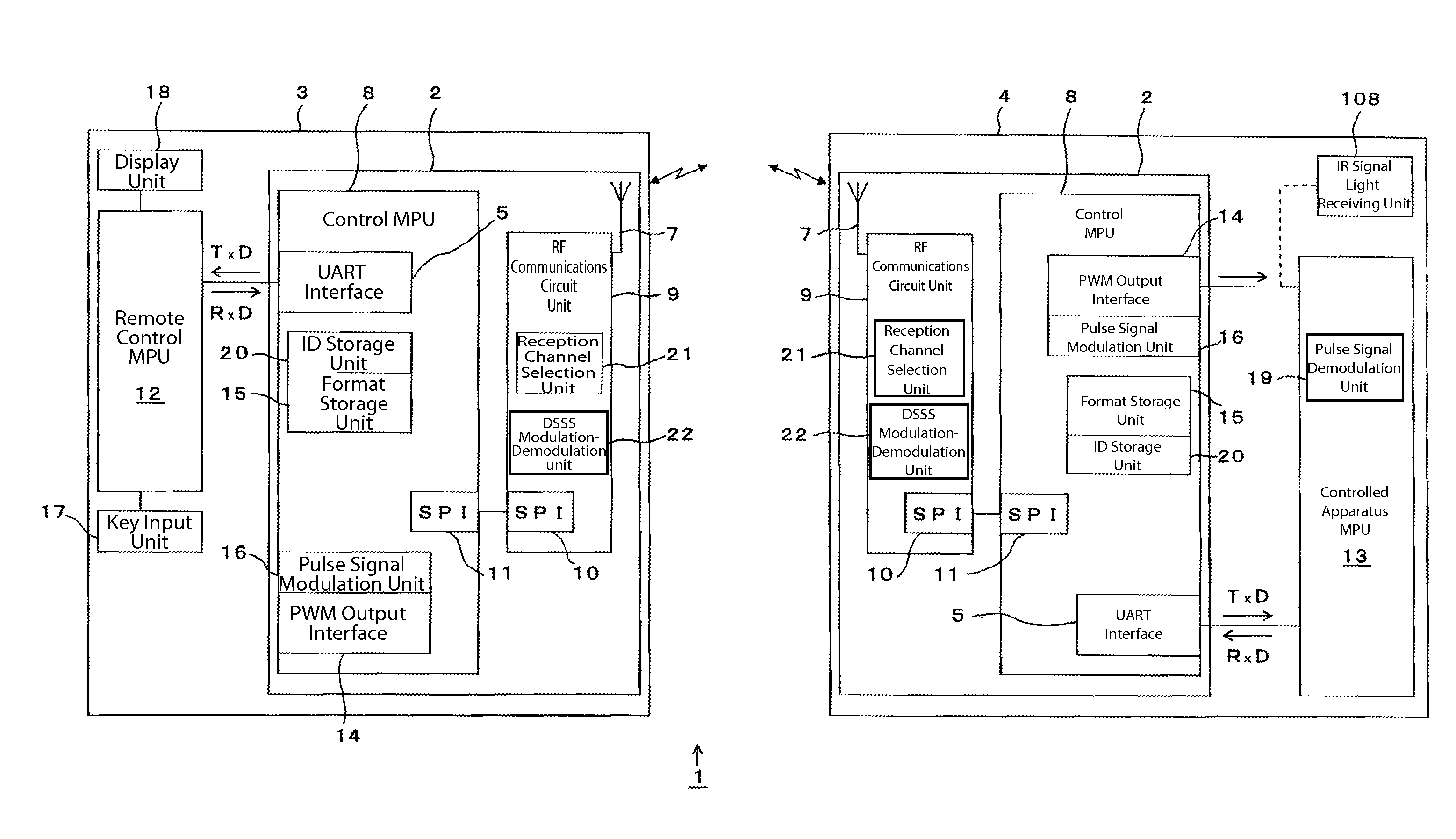
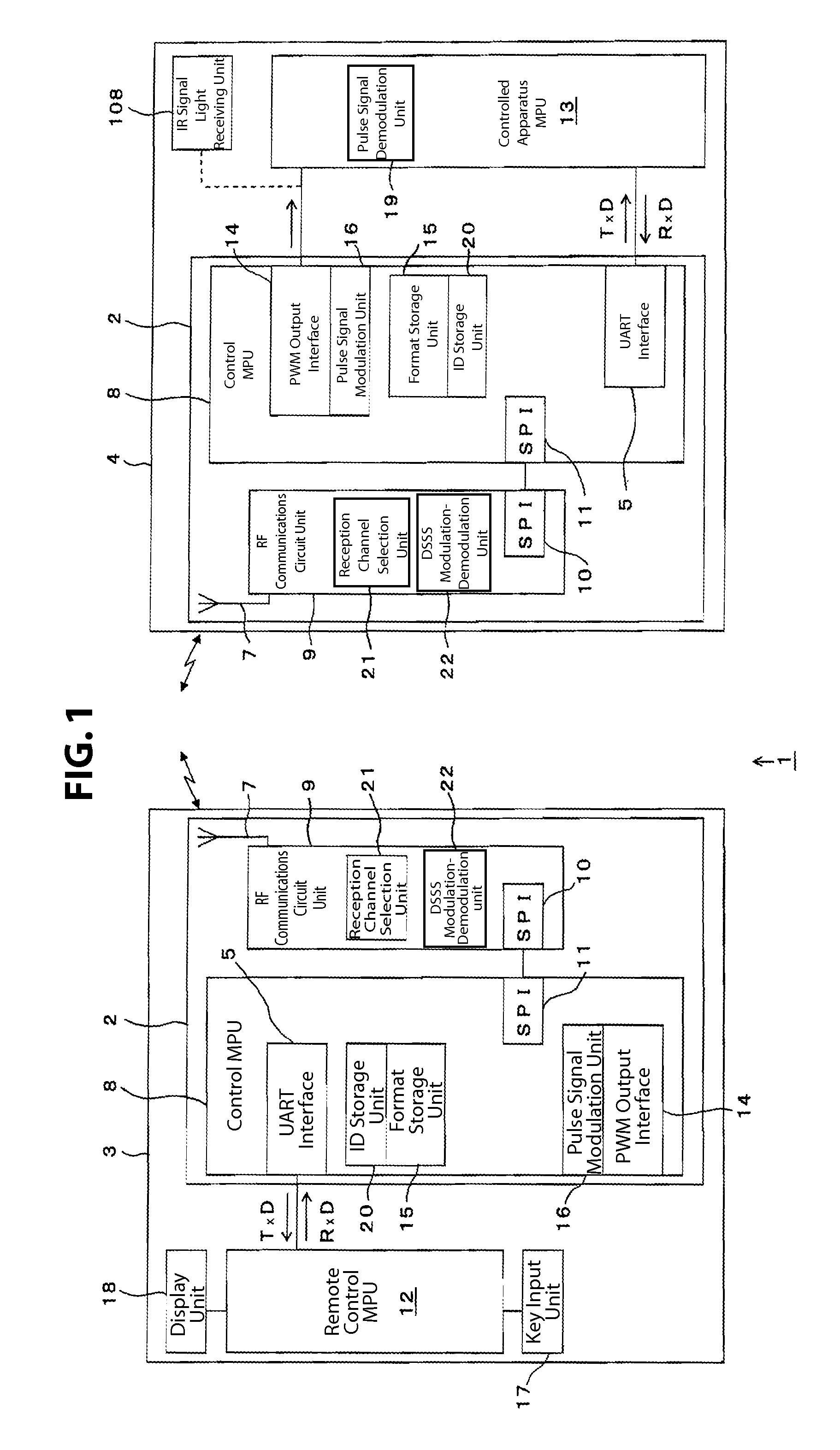
[0045]The following table provides a key to the reference numerals and elements depicted in the drawings.[0046]1 RF communications system[0047]2 RF communications module (RF transmitting circuit unit, RF receiving circuit unit)[0048]3 Remote control transmitter[0049]4 Controlled apparatus[0050]7 Printed antenna (transmitter antenna, receiving antenna)[0051]12 Remote control MPU (remote control side control unit)[0052]13 Controlled apparatus MPU (apparatus side control unit)[0053]15 Format storage unit[0054]16 Pulse signal modulation unit[0055]19 Pulse signal demodulation unit

[0056]The following description is directed to an RF communications system 1 in accordance with principles of the present invention, referencing FIG. 1 through FIG. 8. FIG. 1 is a block diagram that shows an RF communications system 1 that comprises a remote control transmitter 3, which is on the RF signal transmitting side, and a controlled apparatus 4, which is on the RF signal receiving side. In the present e...


PUM


Abstract

An RF communications system including a controlled apparatus configured to receive a RF signal transmitted from a remote control transmitter on a channel that the controlled apparatus can receive, without providing a response signal to the remote control transmitter. The RF transmitting circuit unit of the remote control transmitter transmits RF signals on all of a number of selected transmission channels in a wireless frequency band, while the RF receiving circuit unit of the controlled apparatus stands by to receive an RF signal on a channel of the selected channels that has a relatively low electric field intensity.

Description

CROSS-REFERENCE TO RELATED APPLICATION[0001]The present application claims priority from under 35 U.S.C. §119 to Japanese Patent Application No. 2007-015440, filed Jan. 25, 2007, and which is hereby incorporated by reference herein in its entirety.FIELD OF THE INVENTION[0002]The present invention relates to an RF communications system that remotely controls a controlled apparatus via an RF signal that is transmitted from a remote control transmitter.BACKGROUND OF THE INVENTION[0003]Remote control of home appliances, such as air conditioners and televisions, generally makes use of infrared communications (IR communications), wherein an infrared control signal (IR signal) is transmitted from a remote control transmitter to the home appliance via infrared rays. However, wireless radio communications (RF communications) systems, wherein control data are carried on a radio frequency (RF) signal that is not constrained by the transmission direction and can be transmitted even if an object...

Claims


Application Information

Patent Timeline
Patent Type & Authority Patents(United States)
IPC IPC(8): G05B11/01G08C19/16H04N5/00H04Q9/00
CPCH04B1/1027H04B1/202H04Q9/00H04L12/12
Inventor OOTSUKA, KENJI
Owner SMK CORP
Learn More