
CMOS image sensor having a crosstalk prevention structure

a crosstalk prevention and image sensor technology, applied in the field of sensors, can solve the problems of image sensor malfunction, low resolution, low resolution, etc., and achieve the effects of low crosstalk, low noise, and low dark curren

Active Publication Date: 2012-03-20
SAMSUNG ELECTRONICS CO LTD
View PDF8 Cites 15 Cited by
  • Summary
  • Abstract
  • Description
  • Claims
  • Application Information

AI Technical Summary

Benefits of technology

This approach effectively reduces crosstalk, dark current, and noise, improving sensitivity and resolution while allowing for high integration density, enabling the production of high-resolution image sensors without image distortion.

Problems solved by technology

However, the requirement for highly integrating the semiconductor device may produce a short distance between adjacent pixels, so that crosstalk is frequently generated.
The optical crosstalk and / or the electrical crosstalk can cause a low resolution and a distorted image of the conventional image sensor.
When the conventional image sensor is produced, the gap between the pixels of the image sensor can be quite narrow and result in the image sensor malfunctioning due to crosstalk.
The optical crosstalk and / or the electrical crosstalk cause low resolution and a distorted image of the conventional image sensor.
Because the conventional image sensor includes a P type substrate, although having good sensitivity, the conventional image sensor has inferior characteristics with respect to dark current (i.e, the relatively small electric current that flows through a photosensitive device when no photons are entering the device) and crosstalk.

Method used


Image

  • CMOS image sensor having a crosstalk prevention structure
  • CMOS image sensor having a crosstalk prevention structure
  • CMOS image sensor having a crosstalk prevention structure

Examples


Embodiment Construction

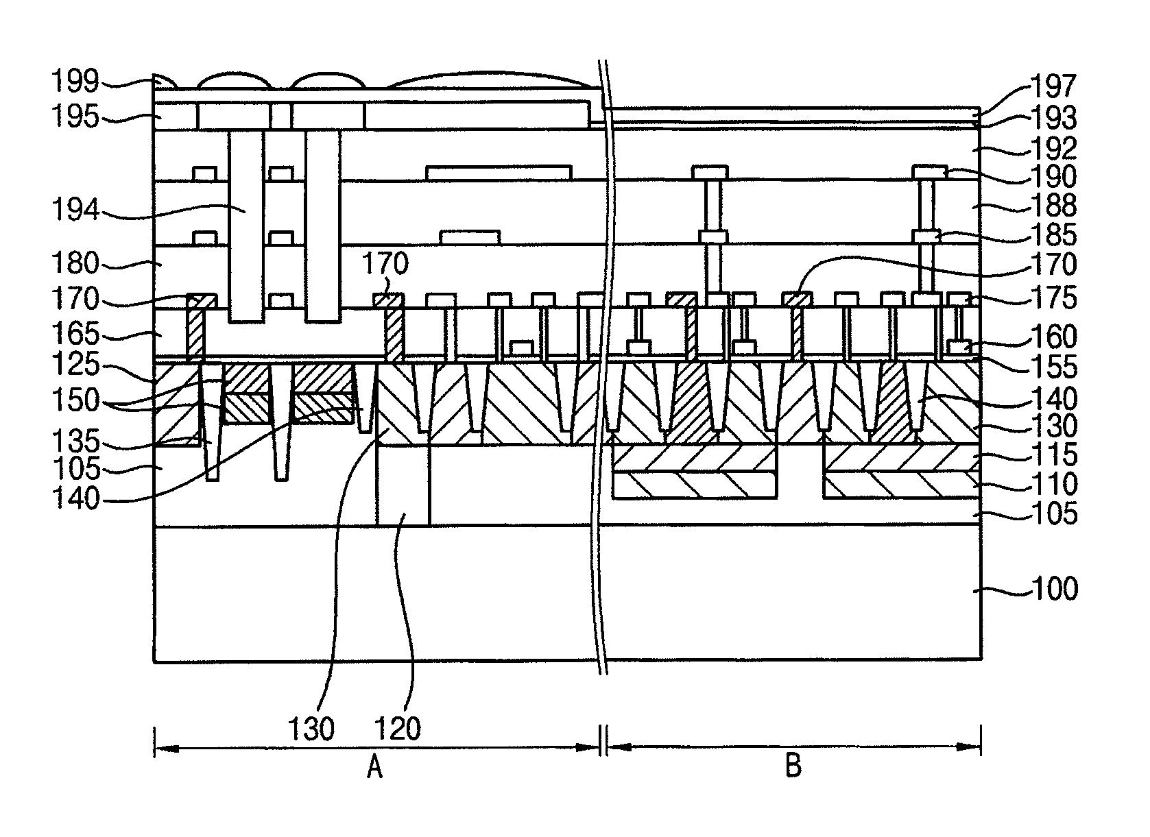
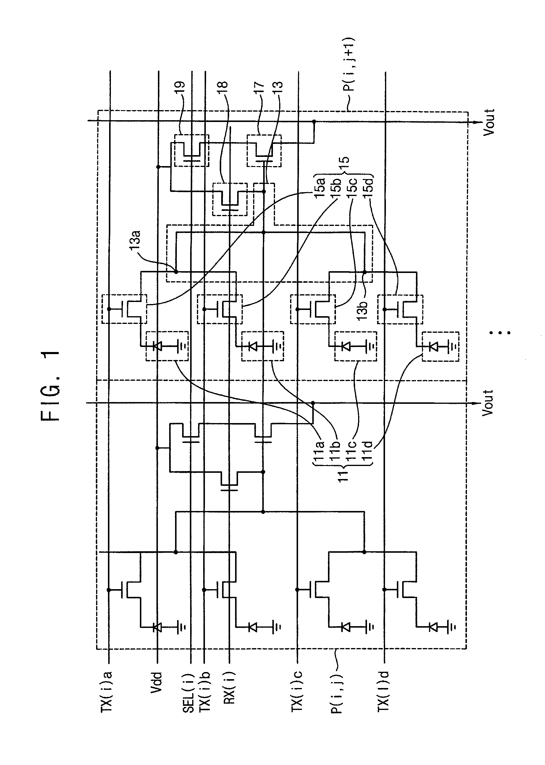
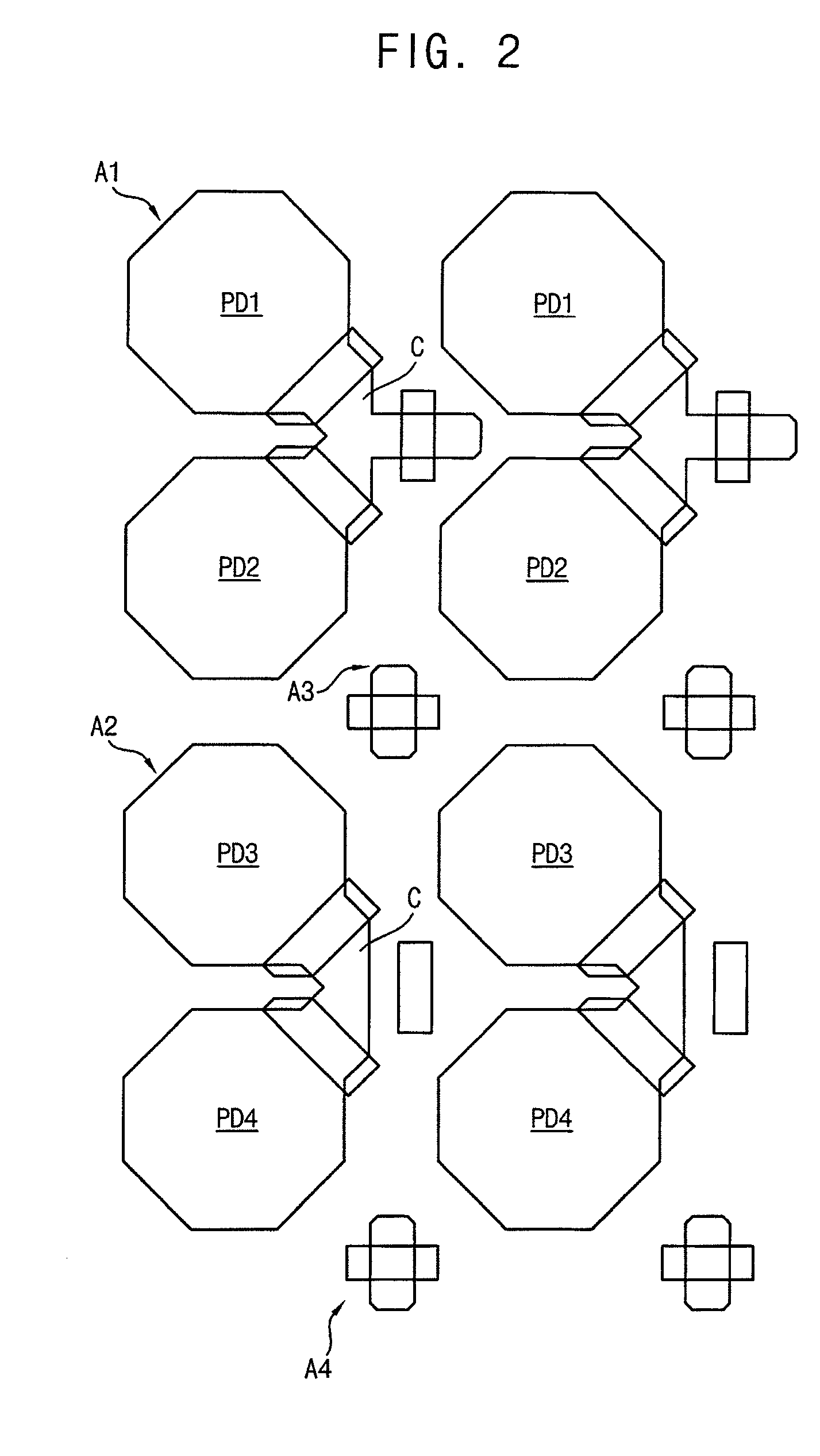
[0041]Various exemplary embodiments will be described more fully hereinafter with reference to the accompanying drawings, in which exemplary embodiments are shown. The present invention may, however, be embodied in many different forms and should not be construed as limited to the exemplary embodiments set forth herein. In the drawings, the sizes and relative sizes of layers and regions are exaggerated for clarity.

[0042]It will be understood that when an element or layer is referred to as being “on,”“connected to” or “coupled to” another element or layer, it can be directly on, connected or coupled to the other element or layer or intervening elements or layers can be present. In contrast, when an element is referred to as being “directly on”, “directly connected to” or “directly coupled to” another element or layer, there are no intervening elements or layers present. Like numerals refer to like elements throughout. As used herein, the term “and / or” includes any and all combination...


PUM

PropertyMeasurementUnit
thicknessaaaaaaaaaa
energyaaaaaaaaaa
energyaaaaaaaaaa

Abstract

In a method of manufacturing a CMOS image sensor, a P type epitaxial layer is formed on an N type substrate. A deep P+ type well layer is formed in the P type epitaxial layer. An N type deep guardring well is formed in a photodiode guardring region. The N type deep guardring region makes contact with the N type substrate and also be connected with an operational voltage terminal. A triple well is formed in a photodiode region and a peripheral circuit region. The triple well is used for forming a PMOS and an NMOS having different operational voltages. An isolation region is formed in the photodiode region. The isolation region in the photodiode region has a depth different from a depth of an isolation region in the peripheral circuit region.

Description

CROSS-REFERENCE TO RELATED APPLICATION[0001]This application claims priority to and the benefit of Korean Patent Application No. 2008-55187, filed on Jun. 12, 2008 in the Korean Intellectual Property Office (KIPO), the entire contents of which is incorporated by reference herein.BACKGROUND[0002]1. Field of the Invention[0003]The present disclosure relates to sensors, and, more particularly, to CMOS image sensors and a method of manufacturing the same.[0004]2. Discussion of the Related Art[0005]Generally, image sensors convert an optical image into an electrical signal. Recently, as the information communication industry and digital electronic devices have developed, image sensors are being widely used in diverse fields such as digital cameras, camcorders, cellular phones, personal communication systems, game devices, guard cameras, medical micro cameras, etc.[0006]Typically, when the degree of integration of a pixel in an image sensor is increased to improve the resolution of the im...

Claims


Application Information

Patent Timeline
Patent Type & Authority Patents(United States)
IPC IPC(8): H01L31/062
CPCH01L27/1463H01L27/14603H01L27/146
Inventor PARK, WON-JEPARK, YOUNG-HOONKIM, UI-SIKSEONG, DAE-CHEOLYOON, YEO-JUKEANG, BO-BAE
Owner SAMSUNG ELECTRONICS CO LTD
Learn More