Audio system

a technology of audio system and audio input, applied in the field of audio system, can solve problems such as the inability to meet the demand of users

Active Publication Date: 2012-03-20
MITSUBISHI ELECTRIC CORP
View PDF6 Cites 5 Cited by
  • Summary
  • Abstract
  • Description
  • Claims
  • Application Information

AI Technical Summary

Benefits of technology

[0009]Thus, it offers an advantage of being able to carry out the playback volume level control that will meet the demand of the user.

Problems solved by technology

The conventional system that stabilizes the general tendency of the playback volume level at every breakpoint of the record information, however, has a problem of being unable to meet such a demand of the user.

Method used


Image

  • Audio system
  • Audio system
  • Audio system

Examples


embodiment 1

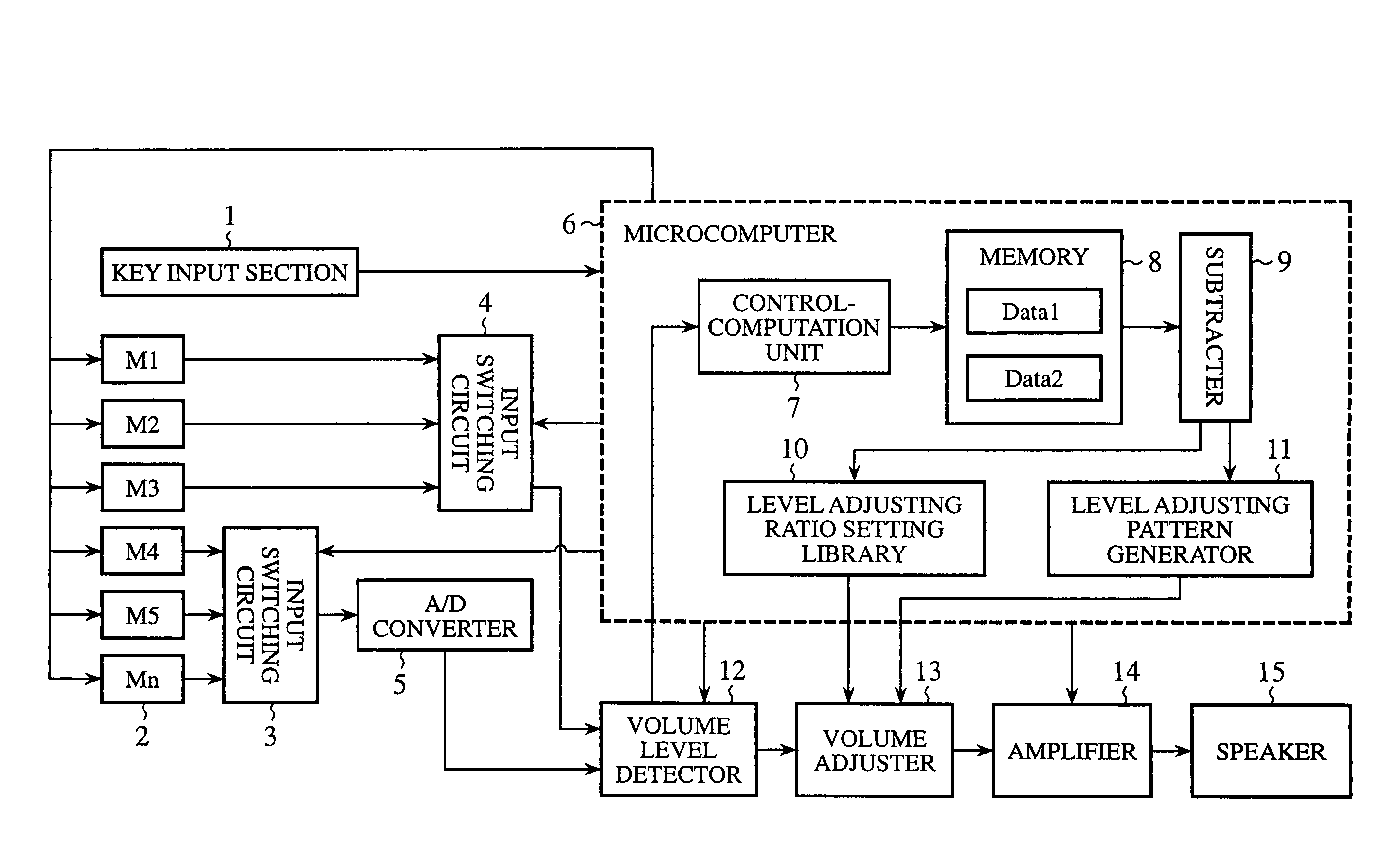
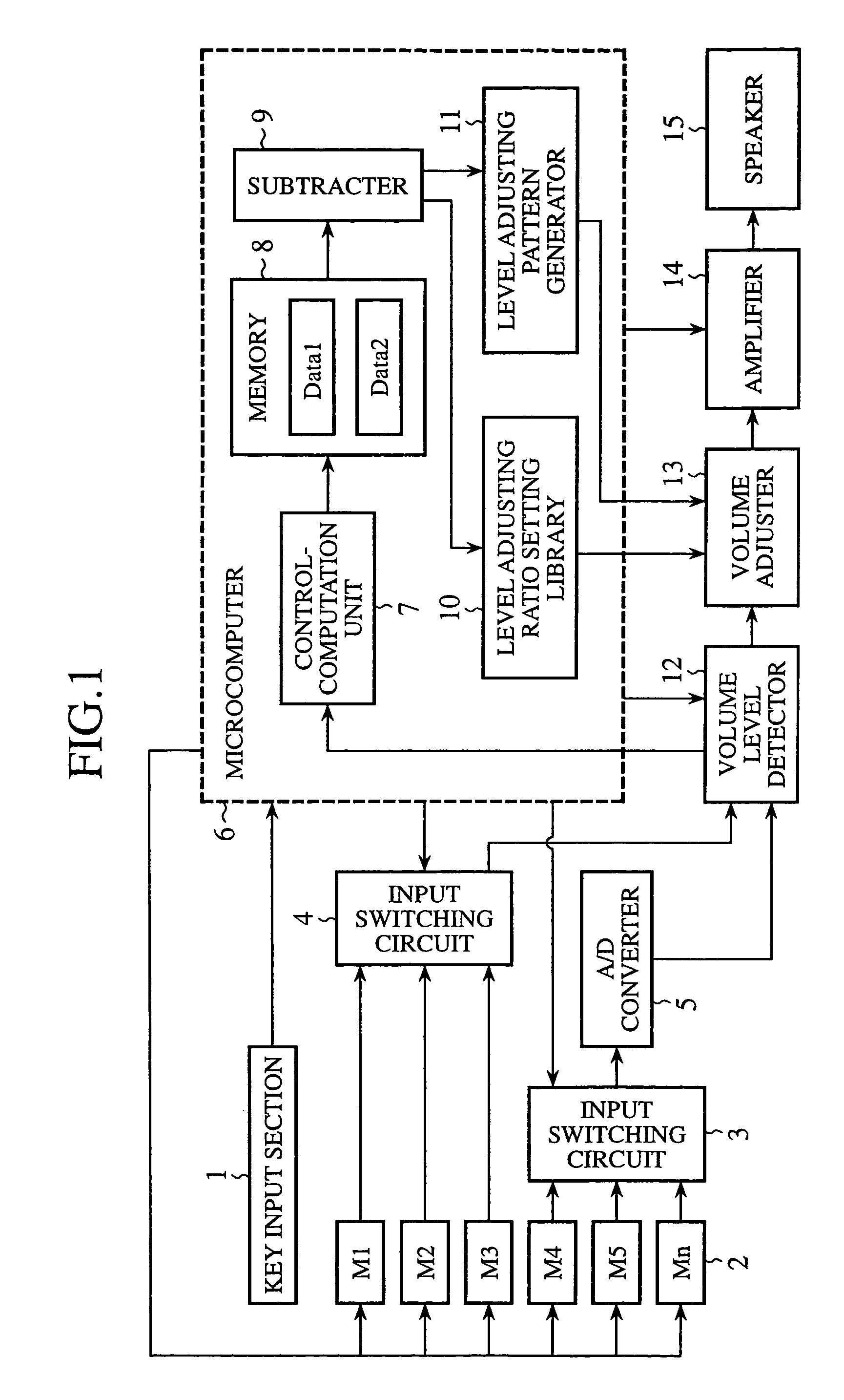
[0029]FIG. 1 is a block diagram showing a configuration of an embodiment 1 of the audio system in accordance with the present invention. In FIG. 1, a microcomputer (sound source selecting means and volume adjusting means) 6 controls the audio system in its entirety. Sound sources 2 are composed of n types of sound sources M1, M2, M3, M4, M5, . . . , and Mn such as a disk player for driving a disk like a CD or MD for providing music information about pieces of music, a tape player for driving a digital cassette tape or analog cassette tape, and a radio receiver for receiving AM, FM or digital sound broadcast. In the example of FIG. 1, it is assumed that the sound sources M1, M2 and M3 provide digital sound data, and the sound sources M4, M5, . . . , and Mn provide analog sound signals.

[0030]A key input section (manipulation means) 1, which is composed of a set of instruction keys and a numeric keypad, is used to input to the microcomputer 6 various operation instructions by user mani...

embodiment 2

[0054]FIG. 8 is a block diagram showing a configuration of an embodiment 2 of the audio control system in accordance with the present invention. In FIG. 8, the same components as those of the embodiment 1 as shown in FIG. 1 are designated by the same reference numerals, and the description thereof is omitted here. In FIG. 8, a playback memory controller 16 is newly added. The playback memory controller 16 stores the sound data of one of the digital sound sources M1-M3, which is output from the input switching circuit 4, or the sound data of one of the analog sound sources M4-Mn except for the radio sound source, which is output from the input switching circuit 3 and is converted to the digital data through the A / D converter 5.

[0055]Next, the operation of the present embodiment 2 will be described.

[0056]The flowcharts of the main routine and subroutines of the microcomputer 6 are substantially the same as those of the embodiment 1. The present embodiment 2, however, differs in that w...

embodiment 3

[0058]FIG. 9 is a block diagram showing a configuration of an embodiment 3 of the audio control system in accordance with the present invention. In FIG. 9, the same components as those of the embodiment 1 as shown in FIG. 1 are designated by the same reference numerals, and the description thereof is omitted here. In FIG. 9, a playback volume level memory 17 is newly added. The playback volume level memory 17 stores the playback volume level of the current sound data. Specifically, the playback volume level of the current sound data, which is detected by the volume level detector 12, is supplied not only to the control-computation unit 7, but also to the playback volume level memory 17 to be stored.

[0059]Next, the operation of the present embodiment 3 will be described.

[0060]FIG. 10 is a flowchart illustrating the playback processing of the microcomputer 6 of the embodiment 3. In the flowchart, the same blocks as those of the playback procedure in the embodiment 1 as shown in FIG. 5...


PUM

PropertyMeasurementUnit
volumeaaaaaaaaaa
volume levelaaaaaaaaaa
playback volume levelaaaaaaaaaa

Abstract

An audio system includes a key input section and a microcomputer, and enables playback volume level control that will meet the demand of a user. The key input section inputs a selection instruction for selecting one of a plurality of sound sources in response to a manipulation. The microcomputer 6, in cooperation with a level adjusting ratio setting library, a level adjusting pattern generator and a volume adjuster, selects the sound source designated by the selection instruction, calculates the level difference ΔP between the playback volume level of the sound data of the current piece of music and that of the next piece of music of the selected sound source, and adjusts the playback volume level of the next sound data in accordance with an adjusting ratio corresponding to the level difference.

Description

BACKGROUND OF THE INVENTION[0001]1. Field of the Invention[0002]The present invention relates to an audio system that controls sound data.[0003]2. Description of Related Art[0004]As for a CD player or CD changer for playing back a CD (compact disk), a technique is proposed which stabilizes its volume level by automatically adjusting the tendency of the playback volume level at every appropriate breakpoint of record information such as a piece of music or disk. One of the disk playback systems of such proposals includes a record volume tendency detecting means for detecting the general tendency of the record volume level in the record information between the breakpoints from a disk playback signal; a playback volume adjusting means for variably adjusting the playback volume level of the disk playback signal; and a playback volume control means for stabilizing the general tendency of the playback volume level of the record information at every breakpoint by controlling the playback vo...

Claims


Application Information

Patent Timeline
Patent Type & Authority Patents(United States)
IPC IPC(8): H04H60/27H04R3/14G11B7/00G11B20/00G11B20/10G11B31/00H04R3/00H04S7/00
CPCG11B20/10527H04H60/04H04S7/00G11B2020/10546G11B2220/2529G11B2220/2545G11B2220/90G11B2220/913H04R2420/01H04S2400/13
Inventor IEDA, KUNIYOMITSUGI, TATSUYAUTSUI, YOSHIHIKO
Owner MITSUBISHI ELECTRIC CORP
Why Eureka
Try Eureka