Light emitting diode (LED) lighting device

a technology of leds and lighting devices, which is applied in semiconductor devices, discharge tube main electrodes, lighting and heating apparatus, etc., can solve the problem of low heat sink performance of leds at the center of the array, and achieve the effect of promoting air movemen

Active Publication Date: 2012-03-27
BX LED LLC
View PDF23 Cites 97 Cited by
  • Summary
  • Abstract
  • Description
  • Claims
  • Application Information

AI Technical Summary

Benefits of technology

[0013]Embodiments of the invention are directed to an LED lighting device comprising a plurality of LEDs mounted on one or more faces of a thermally conducting body. The / each face has at least one opening that is in communication with at least one cavity within the body and the LEDs are mounted around the opening and in thermal communication with a respective face of the body. At least one passage that passes through the body from the at least one cavity to an outer surface of the body is configured such as to promote movement of air through the cavity by thermal convection through the at least one passage thereby to provide cooling of the body and the LEDs. The cavity and passage(s) together operate in a similar manner to a chimney (flue) in which, by the “chimney effect”, air is in drawn in for combustion by the rising of hot gases in the flue. Consequently the cavity and passage(s) can collectively be considered to comprise a flue.
[0017]To increase the flow of air the device advantageously comprises a plurality of passages connecting the cavity to the outer surface of the body. The plurality of passages can be circumferentially spaced and / or axially spaced. The passages can extend in directions at different angles to a line that is parallel with the axis of the body to maximize the flow of air irrespective of the orientation of operation of the device.
[0018]To further assist in the dissipation of heat the body advantageously further comprises a plurality of heat radiating fins (veins) or other heat radiating features extending from a surface of the body. The plurality of heat radiating fins can extend from the outer surface of the body and / or from a surface of the at least one cavity or the one or more passages. The body can be fabricated from any material with a high thermal conductivity (typically ≧150 Wm−1K−1 and preferably ≧200 Wm−1K−1) such as for example copper, aluminum, anodized aluminum, an aluminum alloy, a magnesium alloy or a metal loaded plastics material or a thermally conductive ceramic such as aluminum silicon carbide (AlSiC). Preferably the body has a dark finish, preferably black, to further increase the radiation of heat from the body.
[0022]The devices of the invention find particular application in general lighting where the illumination product will most often be white light. In such applications the light emitting diodes can be white light emitting LEDs that incorporate a phosphor material, so called “white LEDs”. Alternatively, in other arrangements at least one phosphor material can be provided overlying the plurality of light emitting diodes, said phosphor material being operable to absorb at least a part of the light emitted by an associated light emitting diode and to re-emit light of a different wavelength. The phosphor, which is typically in the form of a powder, can be mixed with a light transmissive binder material such as a polymer material (for example a thermally or UV curable silicone or an epoxy material) and the polymer / phosphor then extruded into a sheet. The phosphor sheet can be cut or stamped into appropriately shaped pieces that are then mounted overlying the LEDs. One advantage of separately fabricating a sheet of phosphor-containing material is that it is possible to generate a more consistent color and / or correlated color temperature (CCT) of emitted light since the generation of light by photo-luminescence of the phosphor occurs over a larger area compared to the area when the phosphor is incorporated as a part of the LED package. A further advantage is a reduction in manufacturing costs since a single LED, typically a blue (400 to 480 nm) light emitting LED, is required and the CCT and / or color hue of light generated by the device selected by application of an appropriate sheet of phosphor-containing material. Another advantage is that since the phosphor is not in direct thermal communication with the LED chip this can reduce thermal degradation of the phosphor.

Problems solved by technology

In contrast, in an arrangement that does not include a central cavity and in which the LEDs are arranged as an array, heat generated by LEDs at the center of the array will have a longer thermal conduction path to a heat emitting surface than that of heat generated by devices at the edges of the array, resulting in a lower heat sink performance for LEDs at the center of the array.

Method used


Image

  • Light emitting diode (LED) lighting device
  • Light emitting diode (LED) lighting device
  • Light emitting diode (LED) lighting device

Examples


first embodiment

[0038]A white light emitting LED lighting device 10 in accordance with the invention will now be described with reference to FIGS. 1 to 3 of the accompanying drawings. The LED lighting device 10 is configured for operation with a 110V (r.m.s.) AC (60 Hz) mains power supply as is found in North America and is intended for use as a direct replacement for an incandescent light bulb / reflector lamp.

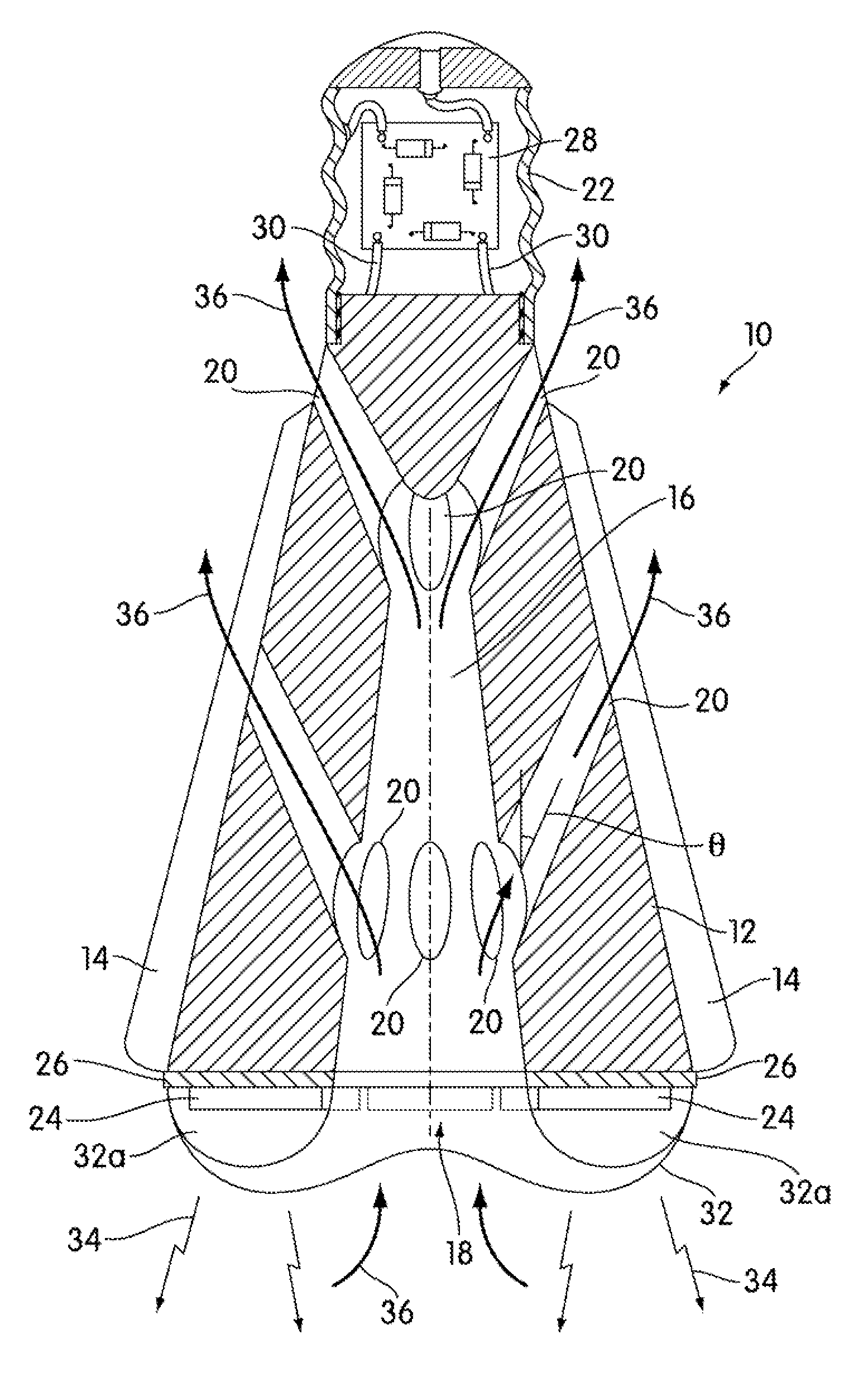
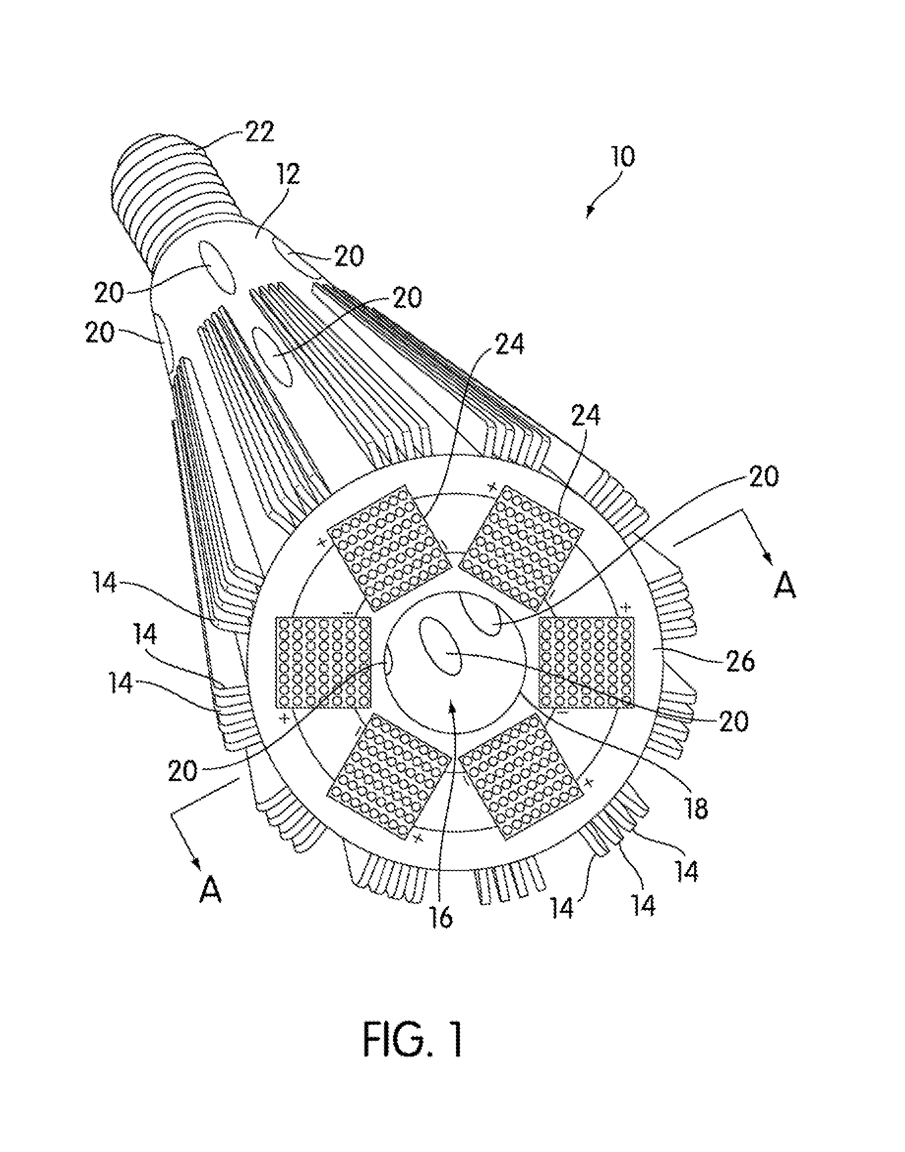
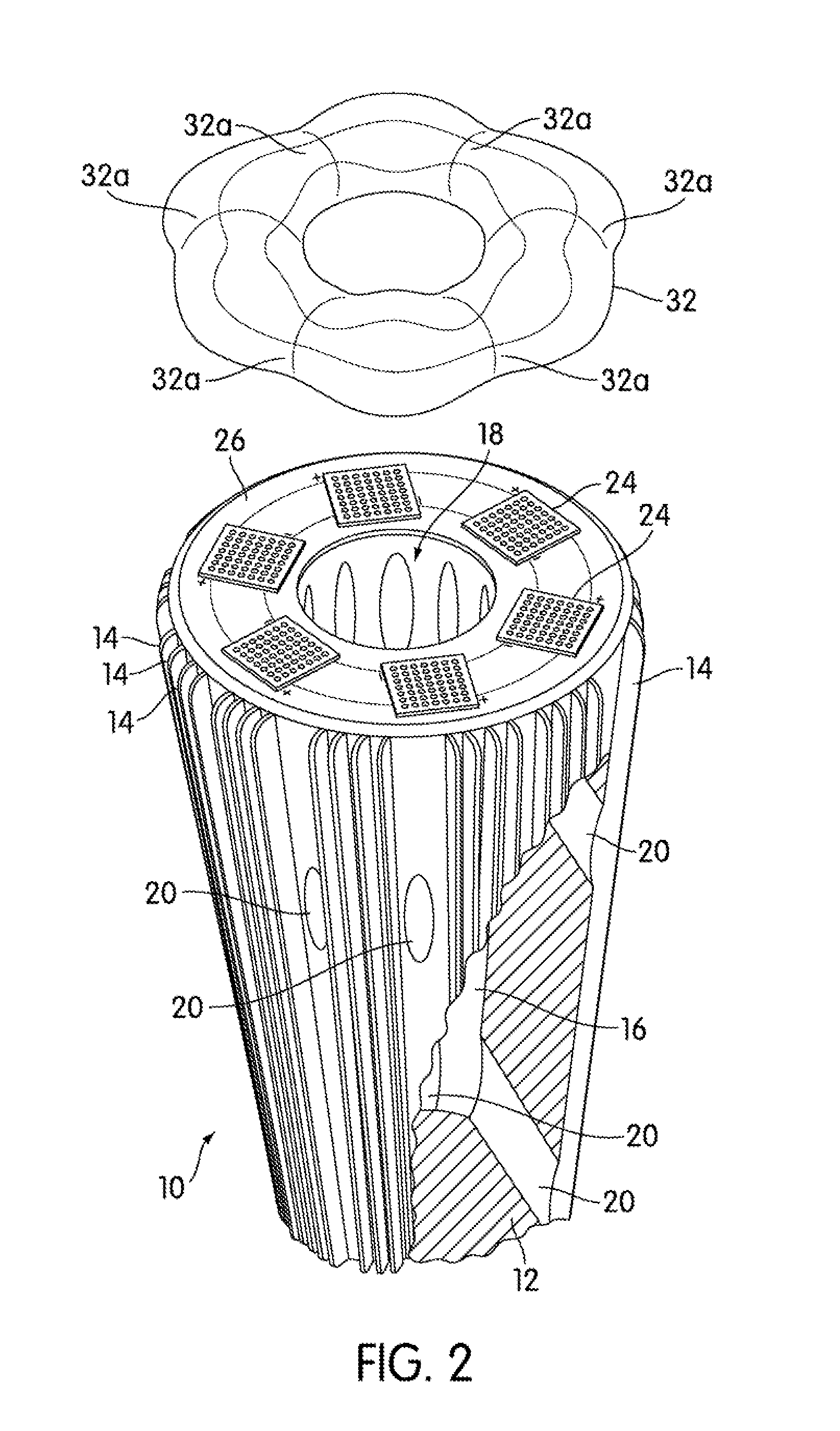
[0039]Referring to FIGS. 1 to 3 the LED lighting device 10 comprises a generally conical shaped thermally conducting body 12. The body 12 is a solid body whose outer surface generally resembles a frustrum of a cone; that is, a cone whose apex or vertex is truncated by a plane that is parallel to the base (substantially frustoconical). The body 12 is made of a material with a high thermal conductivity (typically ≧150 Wm−1K−1, preferably ≧200 Wm−1K−1) such as for example copper (≈400 Wm−1K−1), aluminum (≈250 Wm−1K−1), anodized aluminum, an alloy of aluminum, a magnesium alloy, a metal loaded pla...

second embodiment

[0064]A white light emitting LED lighting device 10 in accordance with the invention will now be described with reference to FIGS. 7 and 8. The LED lighting device 10 is configured for operation with a 110V (r.m.s.) AC (60 Hz) mains power supply and is intended as a direct replacement for a halogen lamp.

[0065]FIG. 7 is a perspective representation of the LED lighting device 10 and comprises a generally frustoconical thermally conducting body 12 having a plurality of latitudinal heat radiating fins (veins) 14 circumferentially spaced around its outer curved surface. The form factor of the body 12 is configured to resemble a standard MR-16 (MR16) body shape enabling the device to be used directly in existing lighting fixtures. The body is made of a material with a high thermal conductivity, that is a thermal conductivity of typically ≧150 Wm−1K−1 and preferably ≧200 Wm−1K−1, such as for example aluminum, anodized aluminum, an alloy of aluminum, a magnesium alloy, a metal loaded plasti...

third embodiment

[0071]A white light emitting LED lighting device 10 in accordance with the invention will now be described with reference to FIGS. 9 and 10. The LED lighting device 10 is configured for operation with a 240V (r.m.s.) AC (50 Hz) mains power supply and is intended as a direct replacement for a incandescent light bulb.

[0072]FIG. 9 is a perspective representation of the LED lighting device 10 and comprises a thermally conducting body 12 that is configured such that its outer surface has a form factor that resembles the envelope (bulb) of a standard incandescent light bulb enabling the device to be used directly in existing lighting fixtures. The body is fabricated of a material with a high thermal conductivity (typically ≧150 Wm−1K−1, preferably ≧200 Wm−1K−1) such as for example aluminum, anodized aluminum, an alloy of aluminum, a magnesium alloy, a metal loaded plastics material or a thermally conductive ceramic. In this embodiment the outer surface of the body is multifaceted and has ...


PUM


Abstract

An LED lighting device comprises: a thermally conducting body having an at least one opening that connects with a cavity within the body and a plurality of LEDs mounted in thermal communication with a face of the body and positioned around the opening. One or more passages pass through the body from the cavity to an outer surface of the body and are configured such that in operation air moves through the cavity by thermal convection thereby to provide cooling of the body. Each passage is configured in a direction that extends in a direction at an angle of about 45° to a line that is parallel with the axis of the body toward the outer surface of the body away from the face. The body can be configured such that its outer surface has a form factor resembling an incandescent light bulb or halogen reflector lamp.

Description

BACKGROUND OF THE INVENTION[0001]1. Field of the Invention[0002]This invention relates to a light emitting diode (LED) based lighting device and in particular to cooling such a device. In particular, although not exclusively, the invention concerns an LED lighting device that can be used as a replacement for a conventional filament lamp such as for example an incandescent light bulb or a halogen reflector lamp. Moreover, the invention concerns an alternating current (AC) driven LED lighting device that can be operated from a high voltage (110 / 220V) power supply.[0003]2. Description of the Related Art[0004]White light generating LEDs, “white LEDs”, are a relatively recent innovation and offer the potential for a whole new generation of energy efficient lighting systems to come into existence. It is predicted that white LEDs could replace filament (incandescent), fluorescent and compact fluorescent light sources due to their long operating lifetimes, potentially many 100,000 of hours,...

Claims


Application Information

Patent Timeline
Patent Type & Authority Patents(United States)
IPC IPC(8): H01J1/02
CPCF21V29/004F21V29/83F21V29/773F21K9/13F21Y2101/02F21Y2111/007F21K9/23F21Y2115/10F21Y2107/40
Inventor LI, YI-QUN
Owner BX LED LLC
Why Eureka
Try Eureka