Electromagnetic actuator driving method

a technology of electromagnetic actuators and actuators, which is applied in the direction of motor/generator/converter stoppers, dynamo-electric converter control, propulsion systems, etc., can solve the problems of difficult cost-effective construction of driving circuits and inability to accurately detect induced electromotive voltages, so as to reduce the number of sensor parts, reduce the number of wiring lines, and reduce the number of component parts

Active Publication Date: 2012-03-27
PANASONIC CORP
View PDF42 Cites 20 Cited by
  • Summary
  • Abstract
  • Description
  • Claims
  • Application Information

AI Technical Summary

Benefits of technology

[0004]In view of the above, the present invention provides an electromagnetic actuator driving method that makes it possible to construct a driving circuit in a cost-effective manner.
[0007]With the electromagnetic actuator driving method of the present invention, the coil is excited only in the first half of the control period. Thanks to this feature, it is possible to reduce the number of component parts of the inverter circuit that applies the alternating voltage to the coil, which makes it possible to construct the inverter circuit in a cost-effective manner. With the electromagnetic actuator driving method of the present invention, the control signals can be detected with no restriction in time, voltage accuracy, current accuracy and the like. This makes it possible to reduce the number of sensor parts. In addition, it is possible to reduce the number of wiring lines leading to the control circuit such as the central processing unit or the like, which makes it possible to construct the control circuit in a cost-effective manner. Therefore, the electromagnetic actuator driving method of the present invention is capable of providing a low-priced driving circuit.

Problems solved by technology

It is, however, impossible to accurately detect the induced electromotive voltage during the time when a magnetizing current or a freewheeling current remains in the coil.
This makes it difficult to construct the driving circuit in a cost-effective manner.

Method used


Image

  • Electromagnetic actuator driving method
  • Electromagnetic actuator driving method
  • Electromagnetic actuator driving method

Examples


Embodiment Construction

[0016]Hereinafter, an electromagnetic actuator driving method in accordance with one embodiment of the present invention will be described with reference to the accompanying drawings which form a part hereof.

[0017][Configuration of Electromagnetic Actuator]

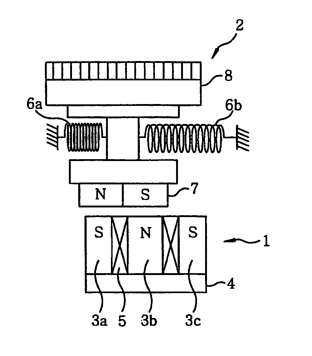
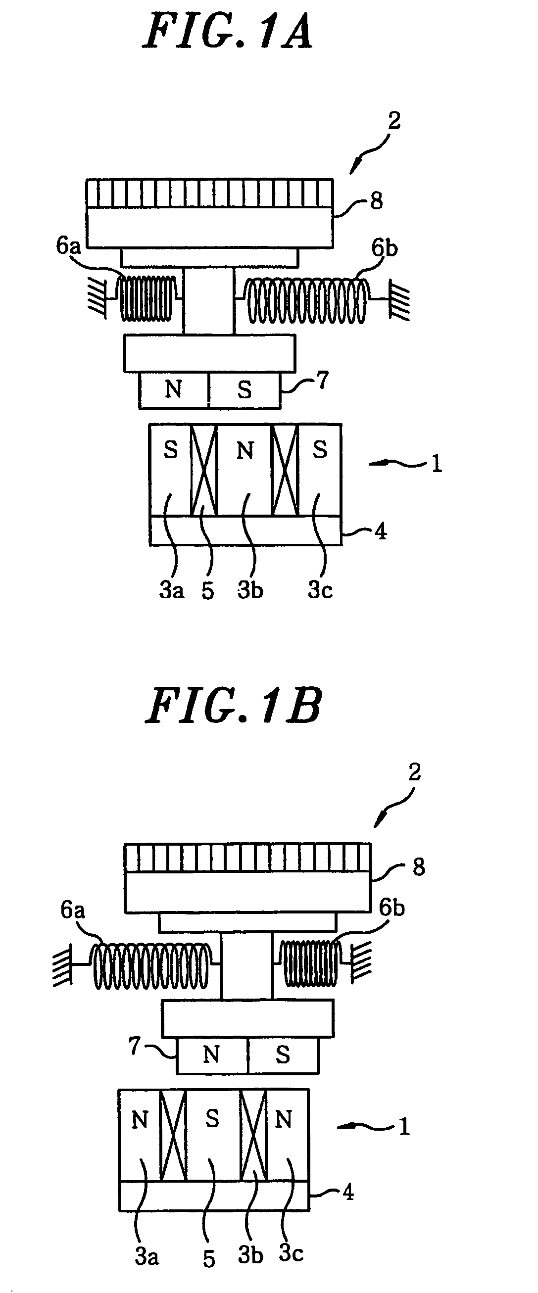
[0018]As shown in FIGS. 1A and 1B, an electromagnetic actuator driven by a method in accordance with one embodiment of the present invention includes a stator 1 and a movable body 2 as its major component parts. The stator 1 includes an E-shaped core 4 provided with three magnetic poles 3a, 3b and 3c and a coil 5 wound on the magnetic pole 3b. The movable body 2 is arranged to oppose the free end surfaces of the magnetic poles 3a, 3b and 3c with a magnetic gap left therebetween. The movable body 2 includes a permanent magnet 7 and a magnetic flux permeation body 8 serving as a back-yoke. The movable body 2 is reciprocatable along the magnetic poles 3a, 3b and 3c and is supported so as to return to the central position of a moving ...


PUM


Abstract

An electromagnetic actuator includes a stator and a movable body. The stator includes a core provided with magnetic poles and a coil wound on at least one of the magnetic poles. The movable body includes a permanent magnet and supported in such a manner as to make reciprocating in a direction perpendicular to a direction in which the permanent magnet opposes the magnetic poles. The movable body is reciprocated upon applying an alternating voltage to the coil. An electromagnetic actuator driving method for driving the electromagnetic actuator includes performing feedback control of the alternating voltage in which the alternating voltage is applied to the coil during a first half of a control period and in which an induced electromotive force generated in the coil during a second half of the control period is used as a control signal.

Description

FIELD OF THE INVENTION[0001]The present invention relates to a method for driving a vibrating-type electromagnetic actuator preferably applicable to an electric shaver and designed to cause a movable body to make reciprocating movement.BACKGROUND OF THE INVENTION[0002]A driving circuit for a vibrating-type electromagnetic actuator is known in the art as a driving circuit that drives a resonance system capable of converting or preserving energy through the use of the elasticity of an elastic body and the inertia of a movable body with mass. The vibrating-type electromagnetic actuator includes a stator with a coil, a movable body with a permanent magnet, and a frame portion for reciprocatably supporting the movable body through a spring, the stator being fixed to the frame portion. The driving circuit for this vibrating-type electromagnetic actuator reciprocates the movable body through sensorless feedback control of the application time of an alternating voltage applied to the coil. ...

Claims


Application Information

Patent Timeline
Patent Type & Authority Patents(United States)
IPC IPC(8): H02P1/00H02P3/00H02K33/16H02P25/06
CPCH02K33/14H02P6/008H02P6/182H02P25/027H02P2203/09H02P6/26H02P25/032
Inventor IZUMI, TOMOHIROIBUKI, YASUO
Owner PANASONIC CORP
Why Eureka
Try Eureka