Supercharge Your Innovation With Domain-Expert AI Agents!

Multi-slicing horizontal synchronization signal generating apparatus and method

a horizontal synchronization and signal generation technology, applied in the field of video clocks, can solve the problems of affecting the visual effects of users, rising to the misjudgment of the slicer, and inevitably distorted horizontal synchronization signals in video signals

Active Publication Date: 2012-03-27
XUESHAN TECH INC
View PDF57 Cites 0 Cited by
  • Summary
  • Abstract
  • Description
  • Claims
  • Application Information

AI Technical Summary

Benefits of technology

"The invention is a device and method for generating horizontal synchronization signals. It uses a slicer to detect edges in a video signal and generate two detection signals based on different voltage levels. A phase detector then detects the phase difference between the two detection signals and a reference time point. A calibration circuit generates a calibration signal based on the phase differences and adjusts the phase of the second horizontal synchronization signal accordingly. This allows for adaptive adjustment of the phase calibration range of the horizontal synchronization signal. The technical effect of this invention is improved synchronization and accuracy in video processing."

Problems solved by technology

However, during a transmission process of video signals, a horizontal synchronization signal in a video signal is inevitably distorted due to channel effects, rising to misjudgment of the slicer 11.
Suppose the NCO 14 calibrates by a small range, a relatively long adjustment period is needed after switching channel for the picture to restore to normal, hence undesirably affecting a user's visual effects.
Jitter is much likely resulted owing to unsatisfactory calibration of the phase of the horizontal synchronization signal.

Method used


Image

  • Multi-slicing horizontal synchronization signal generating apparatus and method
  • Multi-slicing horizontal synchronization signal generating apparatus and method
  • Multi-slicing horizontal synchronization signal generating apparatus and method

Examples


Embodiment Construction

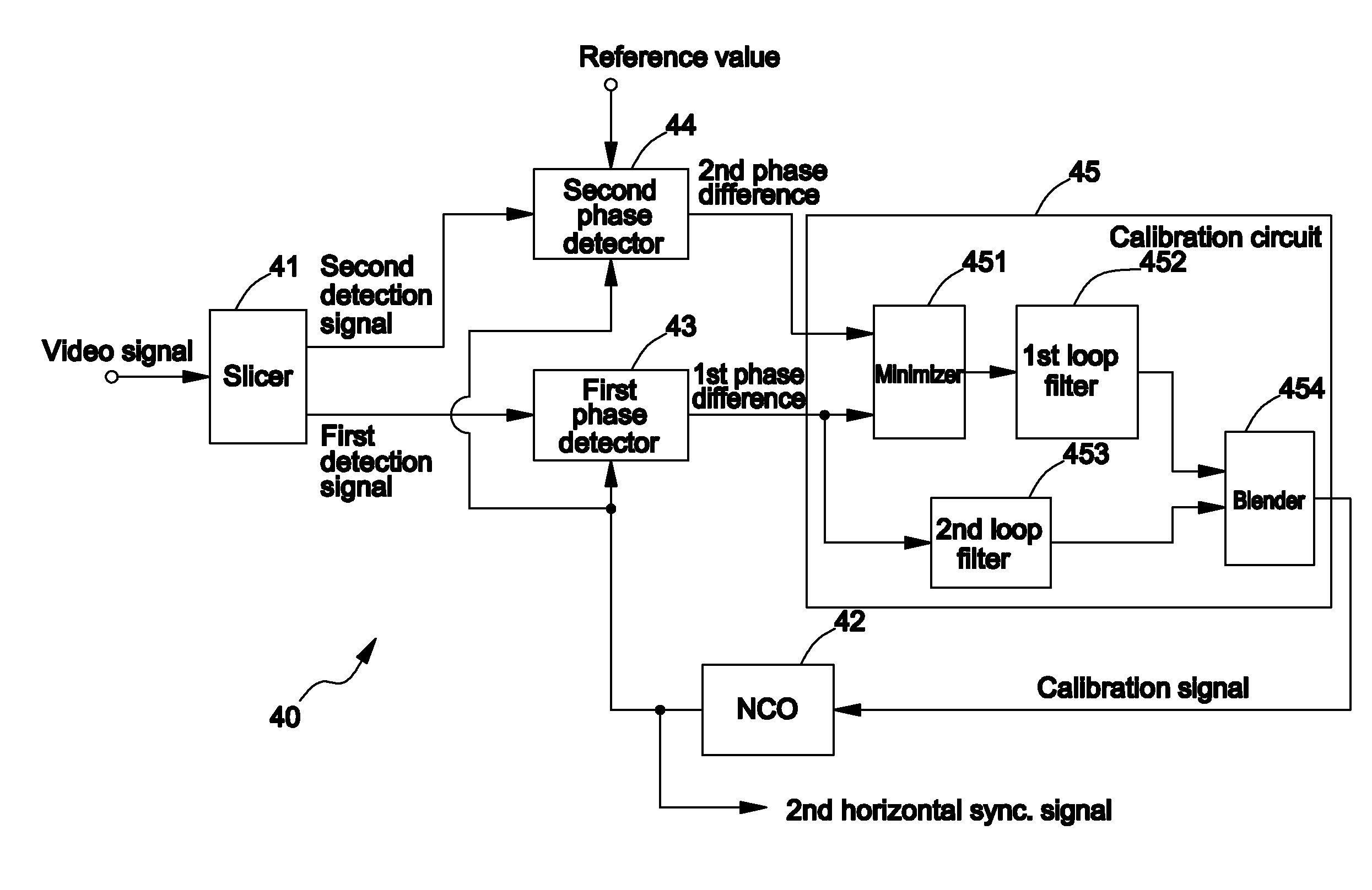
[0019]FIG. 4 shows a block diagram of a multi-slicing horizontal synchronization signal generating apparatus 40 according to one preferred embodiment of the invention, comprising a slicer 41, a numerically controlled oscillator (NCO) 42, a first phase detector 43, a second phase detector 44, and a calibration circuit 45. The slicer 41 performs edge detection on a video signal having a first horizontal synchronization signal, and generates a first detection signal and a second detection signal according to a first voltage level and a second voltage level, respectively. The video signal may be a CVBS signal, a luminance signal in a Y / C signal, or a luma signal in a YPbPr signal. In this embodiment, according to the first voltage level and the second voltage level, the slicer 41 performs falling edge detection on the video signal. That is, when the slicer 41 detects a voltage value of the video signal crossing the first voltage level (or the second voltage level) from high to low, the ...


PUM


Abstract

A multi-slicing horizontal synchronization signal generating apparatus and method is provided. The apparatus includes a slicer, a numerically controlled oscillator (NCO), a first phase detector, a second phase detector and a calibration circuit. The slicer performs edge detection on a video signal having a first horizontal synchronization, and generates a first detection signal and a second detection signal according to a first voltage level and a second voltage level, respectively. The NCO generates a second horizontal synchronization signal. The first phase detector detects a first phase difference between the first detection signal and the second horizontal synchronization signal, and the second detector detects the second phase difference between the second detection signal and a reference time point. The calibration circuit generates a calibration signal according to the first phase difference and the second phase difference. The NCO adaptively adjusts the phase of the second horizontal synchronization signal according to the calibration signal.

Description

FIELD OF THE INVENTION[0001]The present invention relates to a video clock, and more particularly, to a multi-slicing horizontal synchronization signal generating apparatus and method.BACKGROUND OF THE INVENTION[0002]A current analog television such as an LCD TV or a plasma TV, in order to display video signals like composite video broadcast signals (CVBS) on a screen, requires horizontal and vertical synchronization signals. FIG. 1 shows the structure for generating horizontal synchronization signals by a prior analog television. A slicer 11 receives a CVBS signal, and produces a pulse signal when the CVBS signal crosses a specific voltage level from high to low to indicate that a horizontal synchronization signal in the CVBS signal is detected. The pulse signal is then forwarded to a phased lock loop (PLL) 10, in which a phase detector 12 detects a phase difference between the pulse signal and a horizontal synchronization signal generated by a numerically controlled oscillator (NC...

Claims


Application Information

Patent Timeline
Patent Type & Authority Patents(United States)
IPC IPC(8): H04N5/05
CPCH04N5/126
Inventor KO, CHENG TINGLEE, CHUNG HSIUNG
Owner XUESHAN TECH INC
Features
  • R&D
  • Intellectual Property
  • Life Sciences
  • Materials
  • Tech Scout
  • Unparalleled Data Quality
  • Higher Quality Content
  • 60% Fewer Hallucinations
Learn More