Cone-beam CT imaging scheme

a computed tomography and cone beam technology, applied in the field of xray cone beam computed tomography, can solve problems such as incomplete projection images on the cbct detector, and achieve the effect of reducing noise and reducing nois

Inactive Publication Date: 2012-03-27
THE BOARD OF TRUSTEES OF THE LELAND STANFORD JUNIOR UNIV
View PDF13 Cites 21 Cited by
  • Summary
  • Abstract
  • Description
  • Claims
  • Application Information

AI Technical Summary

Benefits of technology

[0005]In one aspect, the present invention provides a technique for CBCT imaging that significantly reduces both scattering effects and undesired radiation dose to the patient while providing high image quality and accurate image registration for patient positioning and dose calculation. By positioning a patterned lead sheet between the CBCT beam source and the patient, many of the x-rays from the CBCT beam source are blocked, resulting in an incomplete projection image on the CBCT detector. In a preferred embodiment, the beam blocking sheet includes several rectangular lead strips, producing a sequence of parallel illuminated slices corresponding to the gaps between the strips. Since the radiation is partially blocked by the strips, the dose delivered to the patient is significantly reduced, with an additional benefit of reduced scatter signals and increased image quality of the illuminated slices. Although the projection image is incomplete, sufficient registration is still possible using the illumined slices.
[0007]In a preferred implementation, the patterned lead sheet is made of rectangular lead strips whose widths are at least 5 mm and which are separated to form gaps at least 2 mm wide. Preferably, the patterned lead sheet is sufficiently thick to completely block x-rays from passing through the sheet and reduces x-rays reaching the patient from the CBCT beam source by a factor of at least six.
[0010]Preferably, reconstructing the CBCT image slices includes reducing noise introduced by scatter correction. The noise may be reduced by applying a penalized weighted least-squares (PWLS) technique to CBCT image projection data. The PWLS technique may use a cost function involving a variance of scatter-corrected line integral data qc given by var(qc)=pm / (pm−se)2, where pm is measured image projection data and se is a scatter estimate.

Problems solved by technology

By positioning a patterned lead sheet between the CBCT beam source and the patient, many of the x-rays from the CBCT beam source are blocked, resulting in an incomplete projection image on the CBCT detector.

Method used


Image

  • Cone-beam CT imaging scheme
  • Cone-beam CT imaging scheme
  • Cone-beam CT imaging scheme

Examples


Embodiment Construction

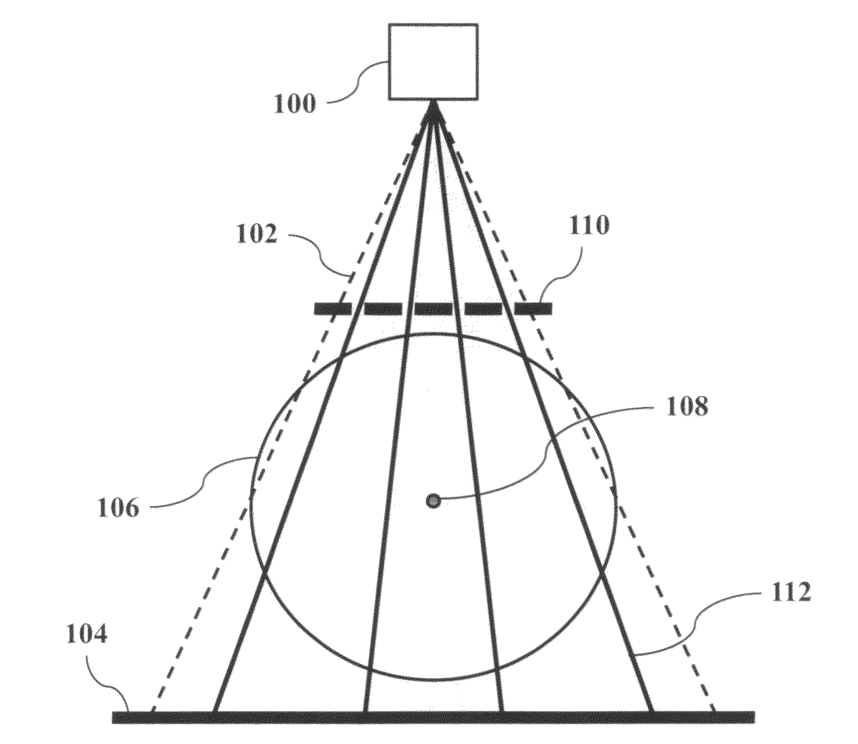
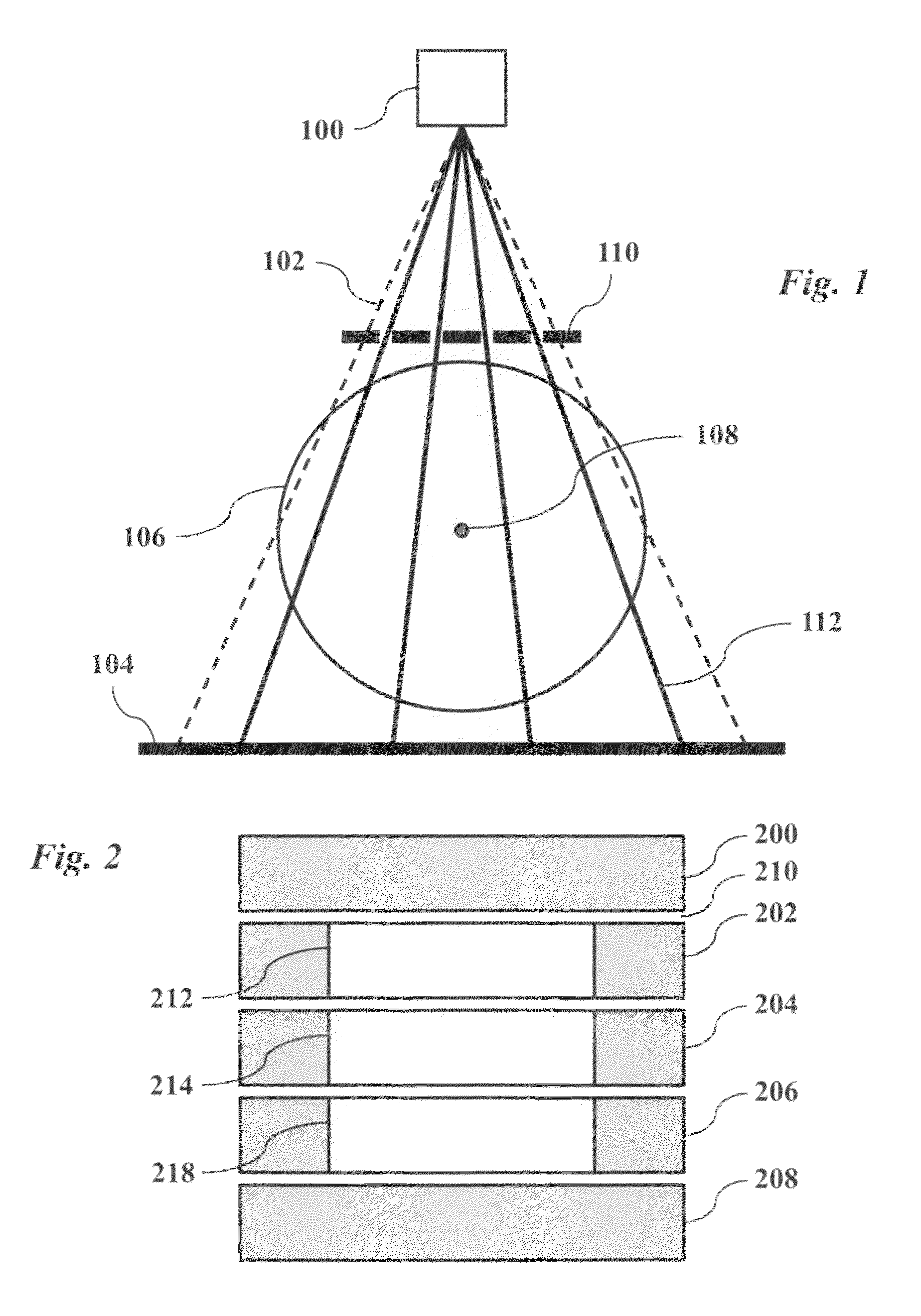
[0017]A cone-beam CT (CBCT) imaging system for the treatment planning of radiation therapy is shown in FIG. 1. As with a conventional CBCT system, an x-ray source 100 generates a cone beam 102 which creates a projection image on detector 104 after passing through a patient 106. The system is designed to rotate around axis 108 during the imaging process. A modified CBCT system according to an embodiment of the invention also includes a patterned beam blocking sheet 110 positioned between source 100 and patient 106 so that a significant portion of the x-rays 102 from source 100 are blocked by the sheet 110 and do not reach patient 106, significantly reducing the radiation dose to the patient. Gaps in the sheet 110 allow portions of the beam 102, such as portion 112, to pass through the sheet and illuminate the patient 106 and detector 104.

[0018]As is apparent, this modified system is easily obtained from an existing system by adding an inexpensive patterned plate. No other modificatio...


PUM


Abstract

A general imaging scheme is proposed for applications of CBCT. The approach provides a superior CBCT image quality by effective scatter correction and noise reduction. Specifically, in its implementation of CBCT imaging for radiation therapy, the proposed approach achieves an accurate patient setup using a partially blocked CBCT with a significantly reduced radiation dose. The image quality improvement due to the proposed scatter correction and noise reduction also makes CBCT-based dose calculation a viable solution to adaptive treatment planning.

Description

CROSS-REFERENCE TO RELATED APPLICATIONS[0001]This application claims priority from U.S. Provisional Patent Application 61 / 067,514 filed Feb. 27, 2008, which is incorporated herein by reference.FIELD OF THE INVENTION[0002]The present invention relates generally to methods and devices for x-ray cone-beam computed tomography (CBCT). More specifically, it relates to techniques for improving image quality in CBCT applications such as radiation therapy.BACKGROUND[0003]Radiation therapy is the use of ionizing radiation in the treatment of cancer. External beam radiotherapy uses diagnostic imaging techniques for treatment planning. A conventional preparation procedure for radiation therapy includes a prior computed tomography (CT) scan using a multi-detector CT (MDCT) scanner for treatment planning and a three-dimensional cone-beam CT (CBCT) scan for patient setup. A three-dimensional registration is performed on the planning CT and the CBCT data to derive appropriate shifts and rotations f...

Claims


Application Information

Patent Timeline
Patent Type & Authority Patents(United States)
IPC IPC(8): A61B6/03
CPCA61B6/032A61B6/466A61B6/542G06T11/005G21K1/02A61N5/103
Inventor ZHU, LEIXING, LEI
Owner THE BOARD OF TRUSTEES OF THE LELAND STANFORD JUNIOR UNIV
Why Eureka
Try Eureka