Transport container for maintaining the temperature of frozen goods

a technology for transporting containers and frozen goods, applied in the field of transport containers, can solve the problems of inability to solve the problem of reducing the temperature of the container, the plastic has to be resistant to the (organic) coolant, and the problem of high vacuum tightness, so as to reduce the cross section of the heat conducting inner wall, reduce the cross section of the conduction cross section, and improve the effect of performan

Active Publication Date: 2012-04-10
SIXT BERNHARD
View PDF27 Cites 7 Cited by
  • Summary
  • Abstract
  • Description
  • Claims
  • Application Information

AI Technical Summary

Benefits of technology

[0008]Accordingly, the invention is based on the object of developing a transport container which is improved with regard to its functionality and handling, ensures a reliable deep-frozen state during storage and transport, completely satisfies the existing transport regulations for frozen biological material, and can be produced without problems.
[0010]Thermal bridges in the region of the access to the sample chamber can be reliably avoided by means of these measures so that a particularly good performance with a long-lasting cooling effect can be achieved. A thermally conducting, metallic connection between the inner wall and the outer wall of the insulation container is avoided by means of the insulation ring, with an influx of heat into the sample chamber through the inner wall being further reduced by means of the long neck opening. Additionally, despite the weight of the cooling container with the coolant hanging on the inner wall, the latter can be designed to be thin due to its elastic mounting, and hence the conduction cross section can be further reduced. Integrating the cooling container furthermore makes a relatively narrow neck opening possible, which likewise reduces the heat conducting inner wall cross section. In addition, heat input due to convection of the air in the cover interior and within the adjacent neck opening is counteracted by only a narrow neck opening gap remaining as a result of the plug with the insulation shaft and, moreover, it being possible to evacuate the trapped quantity of air.
[0011]If the entire insulation container were to be produced from plastics with low thermal conductivity to avoid the thermal bridge between inner wall and outer wall of the insulation container, this would have the disadvantage that said plastic has to be not only resistant against the (organic) coolant, but additionally has to be stable at very low temperatures and highly vacuum-tight. This also means that neither organic degassing of the plastic itself, nor diffusion of the coolant is permitted. This dilemma cannot be solved by installing a separate coolant container made of metal into the plastic container either, because in that case a gap is created between the sample chamber and the neck which is no longer accessible in everyday use. However, due to existing transport regulations for biological samples and tissue samples, and for reasons of hygiene, the sample space must be self-contained and easy to clean should the transport container be reused. For this reason, it is expedient to fixedly integrate the cooling container into the insulation container and to make the wall of the sample chamber and the neck opening, together with the inner wall of the cooling container, from one piece, for example from stainless steel, and thus obtain a seamless sample chamber. In this case, the metallic inner wall additionally has the advantage of an improved heat transfer during the cold-loading prior to the use of the container, that is to say during the transition of the liquid coolant into the solid phase.
[0012]The transport container according to the invention permits a cooling duration of approximately 14 days after cold-loading with complete transition of the coolant into the solid state, and hence permits cold-loading by the supplier, and a “ready to use” system, in which the customer, e.g. a hospital, is supplied with ready-for-use transport containers, which are sent to the customer by the supplier with the required reliability, can be intermediately stored by the customer for up to a week, and can then be sent to a central laboratory by the customer.

Problems solved by technology

If the entire insulation container were to be produced from plastics with low thermal conductivity to avoid the thermal bridge between inner wall and outer wall of the insulation container, this would have the disadvantage that said plastic has to be not only resistant against the (organic) coolant, but additionally has to be stable at very low temperatures and highly vacuum-tight.
This dilemma cannot be solved by installing a separate coolant container made of metal into the plastic container either, because in that case a gap is created between the sample chamber and the neck which is no longer accessible in everyday use.
However, due to existing transport regulations for biological samples and tissue samples, and for reasons of hygiene, the sample space must be self-contained and easy to clean should the transport container be reused.

Method used


Image

  • Transport container for maintaining the temperature of frozen goods
  • Transport container for maintaining the temperature of frozen goods
  • Transport container for maintaining the temperature of frozen goods

Examples


Embodiment Construction

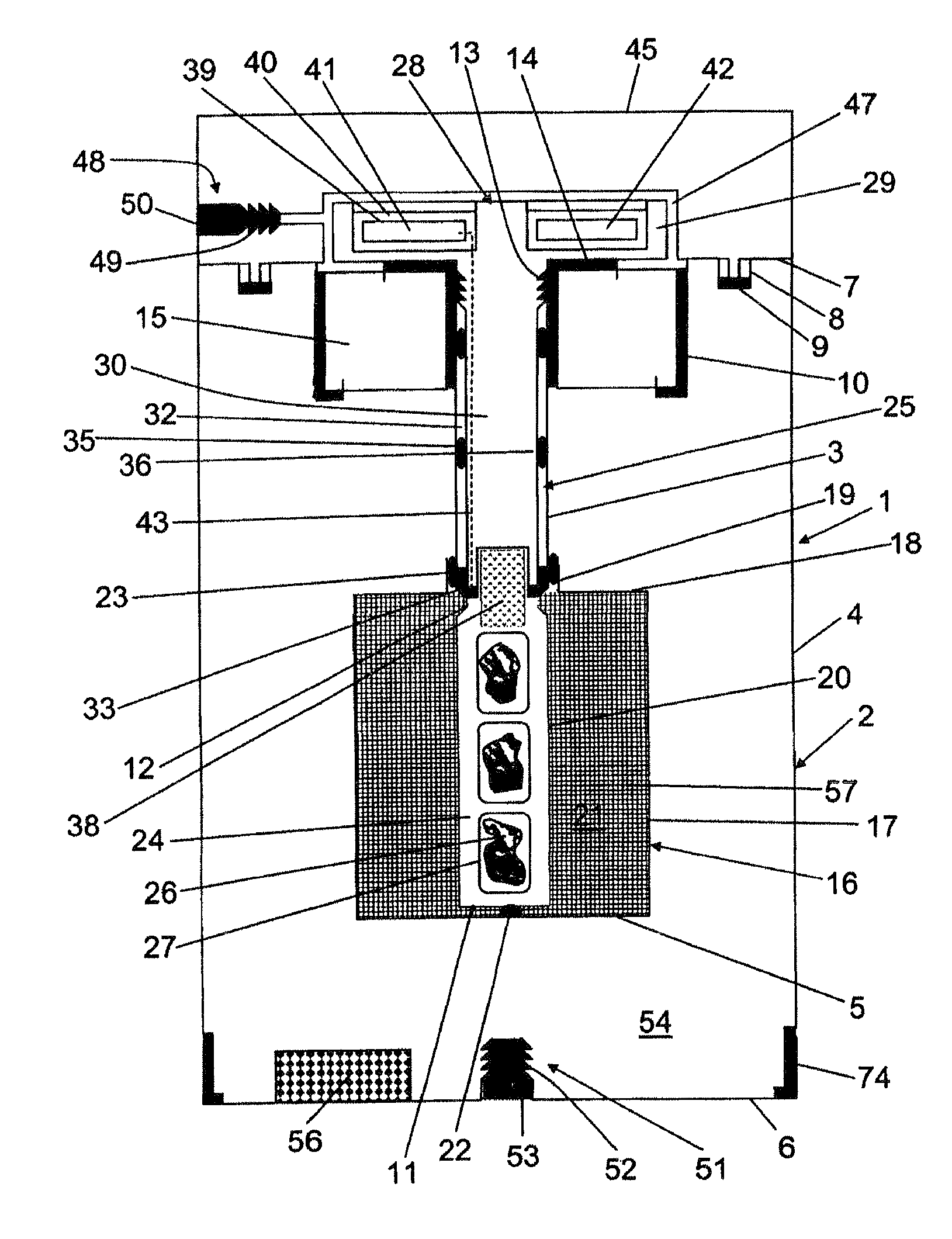
[0031]The transport container 1, drawn in an upright position in FIG. 1, comprises an approximately cup-shaped insulation container 2 with an inner wall 3 and an outer wall 4, as well as an inner base 5 and an outer base 6. The outer base 6 (as is also explained in FIG. 11) is plugged onto the slightly retracted lower end of the outer wall 4 and adhesively bonded or soldered onto the latter.

[0032]At the upper end, the outer wall merges into an interior flange 7, which comprises an annular groove 8 for holding a container seal 9 and which merges into a downwardly extending, peripheral connection web 10.

[0033]The inner wall 3, produced from thin-walled stainless steel, is designed to be thin like a pipe and is provided at its lower end with a chamber base 11; it has a beaded constriction 12 at medium height, supports a female thread 13 at its upper end, and merges directly above this into an outwardly protruding annular flange 14.

[0034]An insulation ring 15 is provided at the upper en...


PUM


Abstract

The invention relates to a transport container (1) comprising a superinsulation in the form of an evacuated insulating container (2) comprising a vacuum maintaining material (55). The transport container is provided with a cooling container (16) comprising a heat-conducting metal wool filling (57) and an organic coolant which undergoes a solid / liquid phase change in the temperature range of between −30° C. and −850° C. and has a heat of fusion of at least 50 J / ml. A slim cylindrical sample chamber (24) is used to receive deep-frozen tissue samples (26), said chamber being surrounded by the cooling container (16) and merging into a long neck opening (25) forming a single component therewith, said opening being largely filled by the insulating shaft (30) of a screwable plug (28) and sealed from the sample chamber (24). The air in the ring gap (32) created can be evacuated by means of an evacuating system (48). The plug (28) is provided with a stopper (38) protruding into the sample chamber (24) and a data logger (41) for recording the temperature in the sample chamber (24). Following the freezing of the coolant, the transport container (1) enables distribution times and intermediate storage of up to 14 days without any risk of damage to the tissue samples (26) received therein.

Description

CROSS-REFERENCE TO A RELATED APPLICATION[0001]This U.S. patent application contains some subject matter which is similar to some subject matter of U.S. patent application Ser. No. 10 / 585,378, filed on Apr. 6, 2007.BACKGROUND OF THE INVENTION[0002]The invention relates to a transport container for maintaining the temperature of frozen goods, in particular frozen biological tissue samples or cell cultures.[0003]Clinical diagnostics and research often require quick analysis of tissue samples in external specialist laboratories in order to obtain results for a decision regarding therapy. The analysis methods used (e.g. RNA analyses, protein markers) are rapidly developing. Deep freezing a sample has proven to destroy the least amount of information contained therein. Since research leads to the discovery of new markers on an almost daily basis, conserving the information is important, and it makes sense not only to subject the sample to the currently available examinations but also to c...

Claims


Application Information

Patent Timeline
Patent Type & Authority Patents(United States)
IPC IPC(8): F25D3/08
CPCA01N1/02A01N1/0273B01L7/04B65D81/3816B65D81/382B65D81/3823F25D3/06B01L9/06B01L2200/18B01L2300/1855B01L2300/1894F25D2201/14F25D2303/08221F25D2331/804F25D3/105
Inventor SIXT, BERNHARD
Owner SIXT BERNHARD
Why Eureka
Try Eureka