Vehicle control apparatus

a technology for controlling apparatuses and vehicles, applied in mechanical apparatuses, instruments, transportation and packaging, etc., can solve problems such as uncomfortable starting of travel and waste of battery power

Inactive Publication Date: 2012-04-10
AISIN AW CO LTD
View PDF9 Cites 24 Cited by
  • Summary
  • Abstract
  • Description
  • Claims
  • Application Information

AI Technical Summary

Benefits of technology

[0008]In view of the above situation, one aspect of the present invention is to provide a vehicle control apparatus capable of creating a state wherein a necessary oil pressure is supplied to a hydraulic system when the vehicle starts to travel.
[0010]With this structure, there is detected a status change of the vehicle due to an operation of the vehicle performed prior to detection of a vehicle start operation by the start operation detecting unit or due to movement of the vehicle, and the electric oil pump starts in response to a wakeup signal being transmitted from the management unit when the status change is detected. That is, since the electric oil pump starts in response to a status change of the vehicle due to an operation of the vehicle performed prior to a start operation or due to movement of the vehicle, the electric oil pump has already started when the start operation is detected. Accordingly, even if a time period from the start operation to the actual start of traveling of the vehicle is short, an oil pressure is supplied to the hydraulic system by the electric oil pump that has started earlier, and thus the concern of delay in supply of oil pressure is eliminated. Therefore, the vehicle control apparatus according to the present invention is able to more reliably create a state that a necessary oil pressure is supplied to the hydraulic system when the vehicle starts to travel.
[0011]The electric oil pump control unit stops the electric oil pump when the wakeup signal is canceled. With this structure, when driving of the electric oil pump is unnecessary, the electric oil pump can be stopped securely by canceling the wakeup signal via a data transmission line.
[0013]In one exemplary embodiment of the present invention, the vehicle drive device is provided with a mechanical oil pump coupled to an input member that inputs drive power of a drive source, and the electric oil pump is used as auxiliary for keeping, or retaining, the oil pressure when the drive source is stopped. In such a drive device in which the electric oil pump is used as auxiliary, the performance of the electric oil pump is kept low in view of costs, and consequently it takes a certain period of time to obtain the rated oil pressure by the electric oil pump. Therefore, the vehicle drive device using the electric oil pump as auxiliary is in an environment that easily allows delay in supply of oil pressure. To such a structure, the present invention can be applied particularly effectively.
[0014]In another exemplary embodiment of the present invention, an electric motor is used as a drive source in the vehicle drive device. The electric motor starts more quickly as compared to an internal combustion engine and the like, and therefore a time period from the start-up to the start of traveling is short. Thus, delay in supply of oil pressure occurs easily. Furthermore, the electric motor is capable of generating maximum torque from the start of traveling, and hence a problem of slipping of friction engagement element such as clutches and brakes that operate by an oil pressure is likely to occur. Due to such reasons, the structure of the exemplary embodiments of the present invention that is capable of avoiding delay in supply of oil pressure becomes more effective when the electric motor is used as a drive source in the vehicle drive device.
[0015]The status changes of the vehicle that should be detected by the vehicle status change detecting unit, include status changes based on an operation of a structural member included in the vehicle body that is performed prior to a vehicle start operation and based on movement of a structural member itself These status changes can be defined as a status change related to the vehicle body. Furthermore, there are status changes based on an operation or movement pertaining to when a driver gets in the vehicle, which is performed prior to the vehicle start operation, and they can be defined as a status change when getting in or out of the vehicle. The status change when getting out of the vehicle is included because getting out of the vehicle by the driver, as a state that there is no longer a possibility that the start operation will be performed, can still be important information for controlling the electric oil pump. The vehicle status change detecting unit detects, as a status change of the vehicle, at least one of the status changes related to the vehicle body and the status changes when getting in or out of the vehicle. Thus, it becomes possible to create a state wherein a necessary oil pressure is supplied to the hydraulic system when the vehicle starts to travel.

Problems solved by technology

When this timing is too close to an actual start of traveling of the vehicle, the vehicle starts to travel with an insufficient oil pressure level, which leads to an uncomfortable start of traveling accompanying incomplete operation of friction engagement elements.
Conversely, starting of the electric oil pump that is too early as compared to the actual start of traveling of the vehicle results in a waste of battery power.
However, when the time period from starting of the drive source to actual starting of traveling of the vehicle is short, the friction engagement elements are engaged before the pressure in the hydraulic system is increased to a sufficient level by the electric oil pump.
This may cause a problem of uncomfortable start of traveling accompanying incomplete operation of the friction engagement elements as described above.
This problem stands out particularly in a situation when most of hydraulic oil of the hydraulic system has dropped in the drain due to a long period of parking or the like.

Method used


Image

  • Vehicle control apparatus
  • Vehicle control apparatus
  • Vehicle control apparatus

Examples


Embodiment Construction

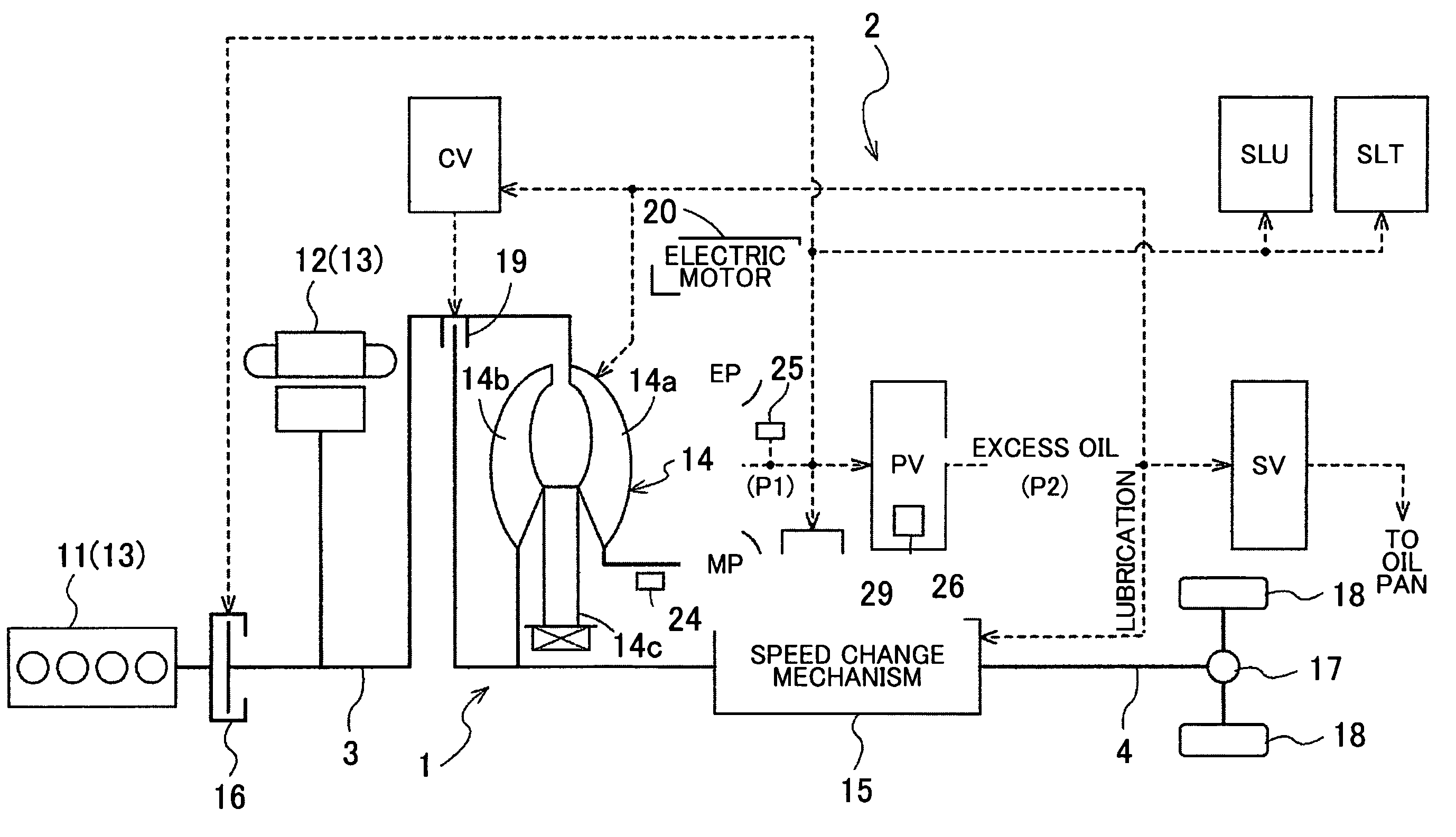
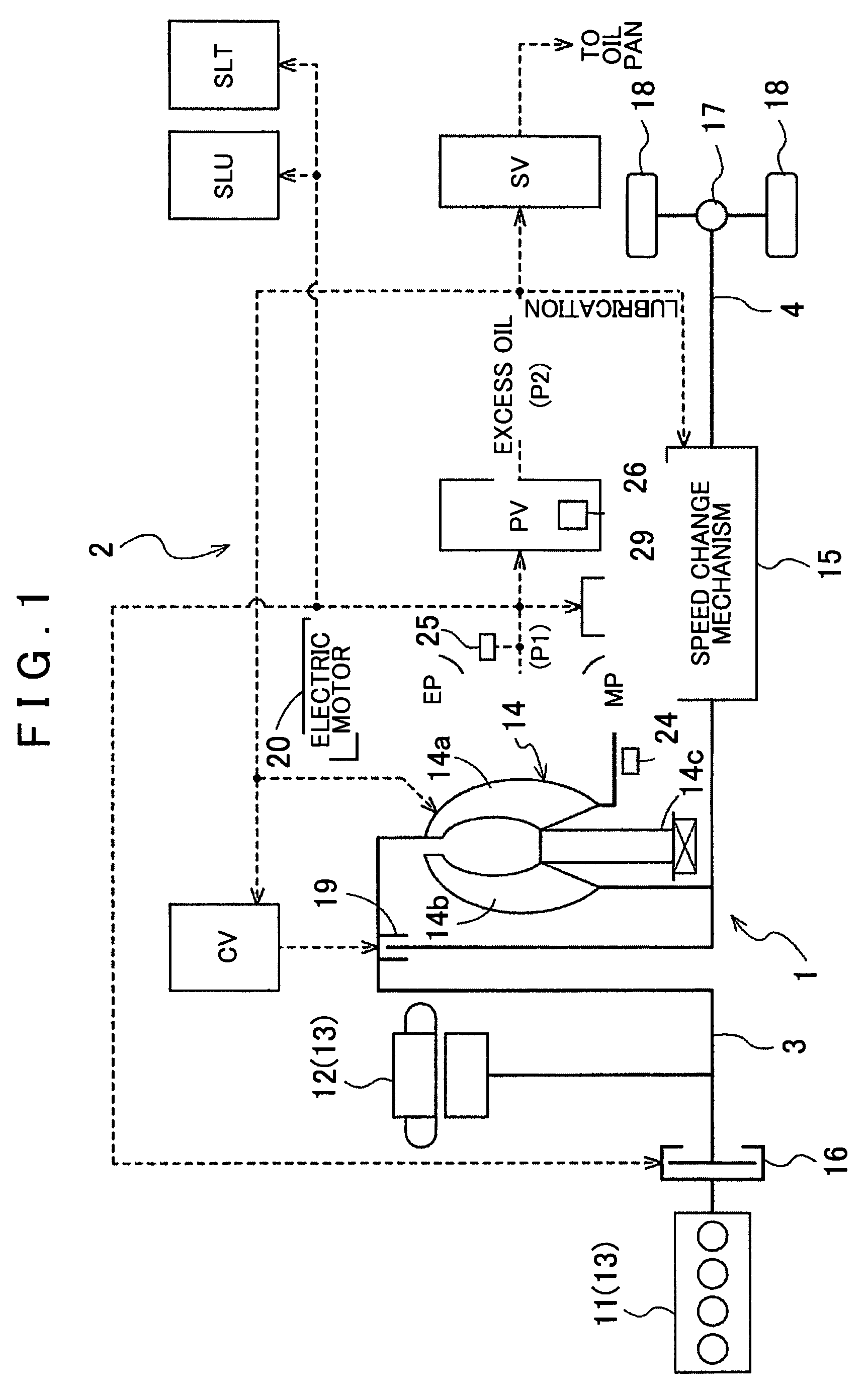
[0024]Hereinafter, explanations will be given using an exemplary embodiment of applying a vehicle control apparatus according to the present invention to a hybrid vehicle. FIG. 1 shows a schematic diagram of schematic structures of a vehicle drive device (hereinafter simply abbreviated as a drive device) 1 and a hydraulic system 2. Note that in FIG. 1, solid lines show transmission paths of drive power, and dashed lines show supply routes of hydraulic oil.

[0025][Overall Structure of the Drive Device]

[0026]First, based on FIG. 1, the schematic structure of the drive device 1 will be explained. As shown in FIG. 1, the drive device 1 includes an engine 11 and a rotary electric machine 12 as a drive power source 13 for driving the vehicle, and the engine 11 is coupled to an input member 3 via a transmission clutch 16. In this exemplary embodiment, the input member 3 is an input shaft arranged coaxially with an output rotary shaft of a crankshaft or the like of the engine 11. The rotary ...


PUM


Abstract

A vehicle control apparatus includes a vehicle drive device having a friction engagement element capable of being engaged and disengaged by an oil pressure generated by an electric oil pump, a start operation detecting unit that detects a start operation of the vehicle, a vehicle status change detecting unit that detects a status change of the vehicle, an electric oil pump control unit that controls the electric oil pump, and a management unit that is connected between the vehicle status change detecting unit and the electric oil pump control unit in a manner capable of transmitting data. The management unit transmits a wakeup signal to the electric oil pump control unit when a status change of the vehicle is detected, and when the wakeup signal is received prior to detection of the start operation, the electric oil pump control unit starts the electric oil pump in response to the wakeup signal.

Description

INCORPORATION BY REFERENCE[0001]The disclosure of Japanese Patent Application No. 2008-117398 filed on Apr. 28, 2008 including the specification, drawings and abstract is incorporated herein by reference in its entirety.BACKGROUND OF THE INVENTION[0002]1. Field of The Invention[0003]The present invention relates to a vehicle control apparatus that includes a vehicle drive device having a friction engagement element capable of being engaged and disengaged by an oil pressure generated by an electric oil pump.[0004]2. Description of The Related Art[0005]In recent automobiles, in particular hybrid vehicles or idling stop vehicles, for the purpose of lubricating and keeping a predetermined oil pressure even when a drive source such as an engine or an electric motor is stopped, an electric oil pump driven by an electric motor is provided for assisting a mechanical oil pump, which is driven by a rotation force of the drive source. In this situation, the timing to start the electric oil pum...

Claims


Application Information

Patent Timeline
Patent Type & Authority Patents(United States)
IPC IPC(8): G06F17/00B60K6/48B60K6/54B60W10/30B60W20/00F16H59/50F16H59/74F16H61/02F16H63/50
CPCB60K6/48B60W10/026B60W10/30B60W30/18027F16H61/0031B60W20/00F16H59/50F16H63/50Y02T10/6221F16H2059/446Y02T10/62B60W20/40
Inventor KOBAYASHI, YASUHIKOSHIBAYAMA, YOSHINORI
Owner AISIN AW CO LTD
Why Eureka
Try Eureka