High-frequency transmission line connection structure, circuit board, high-frequency module, and radar device

a technology of high-frequency transmission lines and connection structures, applied in measurement devices, waveguides, instruments, etc., can solve problems such as the increase of conversion loss associated with mode conversion, and achieve the effect of lowering conversion loss and excellent frequency characteristics of reflected waves

Active Publication Date: 2012-04-17
KYOCERA CORP
View PDF13 Cites 214 Cited by
  • Summary
  • Abstract
  • Description
  • Claims
  • Application Information

AI Technical Summary

Benefits of technology

[0008]The invention has been made in view of such problems, and an object of the invention is to provide a high-frequency transmission line connection structure which has excellent frequency characteristics for reflected waves and is capable of lowering a conversion loss associated with a mode conversion and to provide a circuit board having the connection structure and a high-frequency module having the circuit board and a radar apparatus.

Problems solved by technology

Therefore, electromagnetic waves leak at a connection portion and a conversion loss associated with a mode conversion increases.

Method used


Image

  • High-frequency transmission line connection structure, circuit board, high-frequency module, and radar device
  • High-frequency transmission line connection structure, circuit board, high-frequency module, and radar device
  • High-frequency transmission line connection structure, circuit board, high-frequency module, and radar device

Examples


Embodiment Construction

[0035]Hereinafter, embodiments of the invention are described with reference to the accompanying drawings.

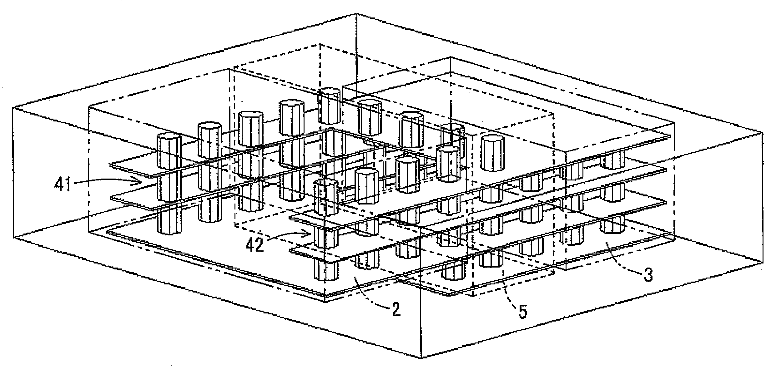
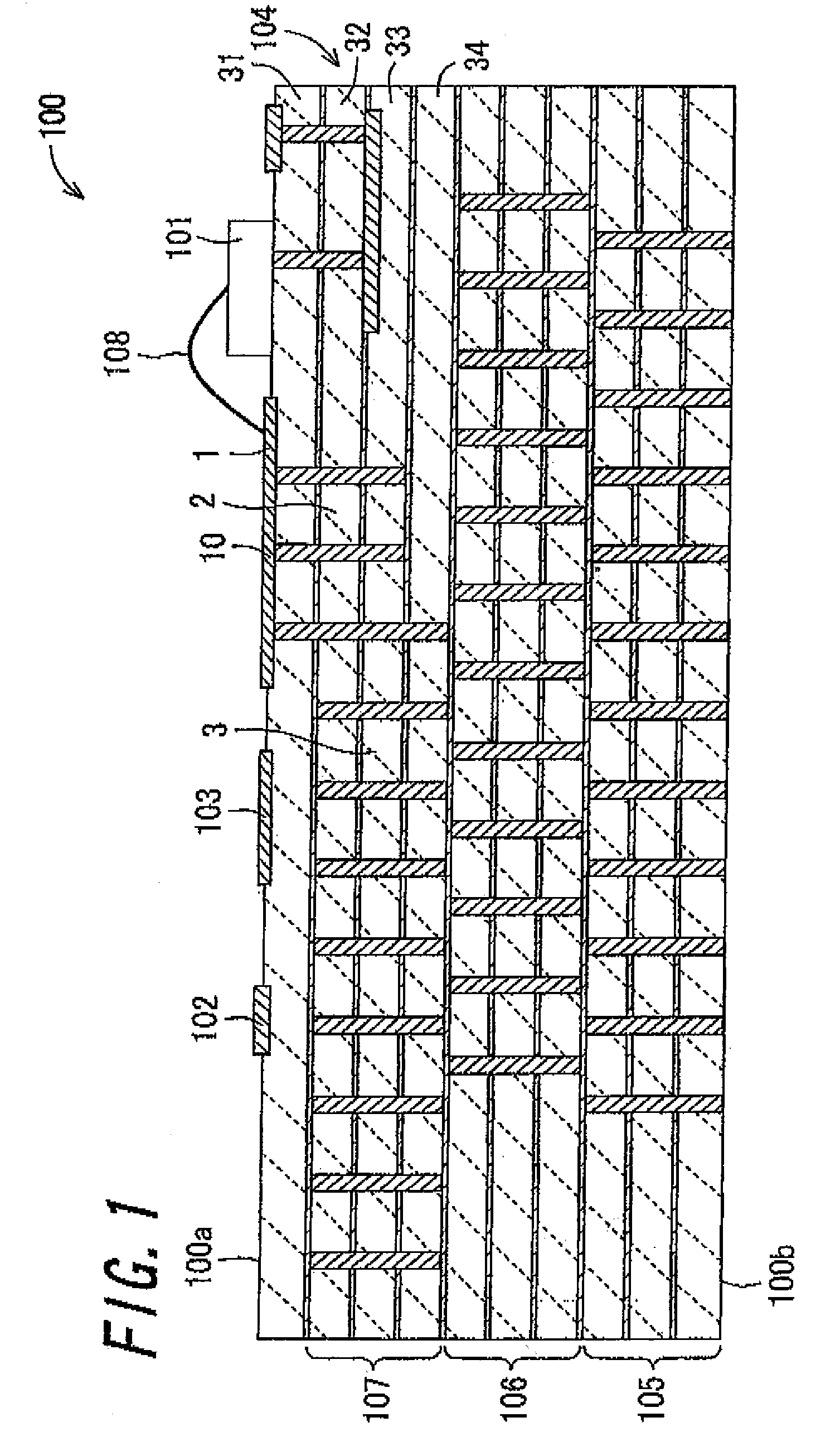
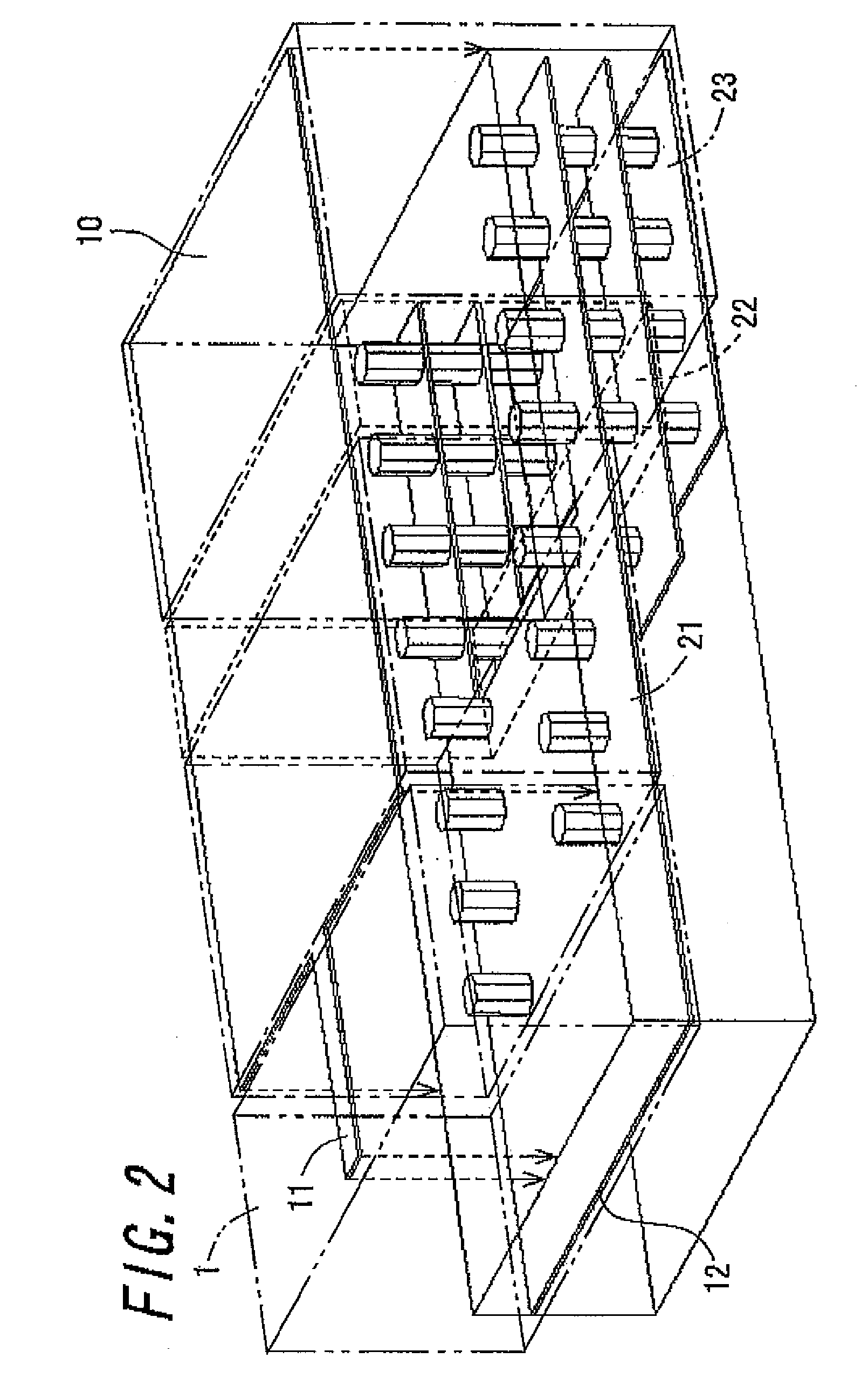
[0036]FIG. 1 is a schematic cross-sectional view showing a high-frequency module 100 including a high-frequency transmission line connection structure according to an embodiment of the invention. FIG. 10 shows a schematic cross section of the connection structure shown in FIG. 1. FIG. 2 is a schematic perspective view showing a connection portion between a microstrip line 1 and a first laminated waveguide 2 in the connection structure shown in FIG. 1. FIG. 3 is a schematic perspective view showing a connection portion between the first laminated waveguide 2 and a second laminated waveguide 3 in the connection structure shown in FIG. 1. FIGS. 4A to 4E are plan views showing the connection structure shown in FIG. 1 exploded for each dielectric layer.

[0037]In FIGS. 2 and 3, illustrations of dielectric layers are omitted for the microstrip line 1, the first laminated waveguide 2, an...


PUM


Abstract

The invention relates to a high-frequency transmission line connection structure, a circuit board having the connection structure, a high-frequency module having the circuit board, and a radar apparatus. A first laminated waveguide sub-line part (21) includes a pair of main conductor layers that oppose each other in a thickness direction with a dielectric layer (31) having the same thickness as a dielectric layer (31) of a microstrip line (1) interposed therebetween. A second laminated waveguide sub-line part (22) includes dielectric layers (31, 32) thicker than the dielectric layer of the first laminated waveguide sub-line part (21). A laminated waveguide main-line part (23) includes dielectric layers (31, 32, 33) thicker than the dielectric layers of the second laminated waveguide sub-line part (22). A conversion part (10) connected to the microstrip line (1) is formed by integrating with an upper main conductor layer constituting the respective line parts.

Description

CROSS-REFERENCE TO THE RELATED APPLICATIONS[0001]This application is a national stage of international application No. PCT / JP2008 / 073872, filed on Dec. 27, 2008, and claims the benefit of priority under 35 USC 119 to Japanese Patent Application No. 2007-341477, filed on Dec. 28, 2007, the entire contents of which are incorporated herein by reference.TECHNICAL FIELD[0002]The present invention relates to a connection structure between a high-frequency transmission line conductor and a laminated waveguide which are mainly used in the microwave band or the millimeter wave band, a circuit board having the connection structure, and a high-frequency module having the circuit board, and a radar apparatus.BACKGROUND ART[0003]In circuit design of millimeter wave circuits, there is known a structure in which a microstrip line, which is converted from a high-frequency transmission line such as a microstrip line connected to a semiconductor device or a coplanar line connected to a semiconductor ...

Claims


Application Information

Patent Timeline
Patent Type & Authority Patents(United States)
IPC IPC(8): H01P3/00G01S7/03G01S13/02H01P1/04H01P3/08H01P3/12H01P5/02H01P5/107H04B1/38
CPCG01S7/032G01S13/02H01P1/20345H01P3/081H01P3/121H01P5/107
Inventor MIYAZATO, KENTAROHAYATA, KAZUKIKISHIDA, YUJI
Owner KYOCERA CORP
Why Eureka
Try Eureka