Conductive line communication apparatus and conductive line radar system and method

a communication apparatus and conductive line technology, applied in the field of communication systems and methods, can solve the problems of loss in distance signal travel, complex and expensive development and field of modern communication systems and radar systems,

Inactive Publication Date: 2012-04-17
SENSIS CORPORATION
View PDF16 Cites 661 Cited by
  • Summary
  • Abstract
  • Description
  • Claims
  • Application Information

AI Technical Summary

Benefits of technology

[0019]In some embodiments, the mono-static conductive line radar system further comprises an accelerometer to measure at least one of wind movement and vibration of the power line, and the at least one signal processor removes effects of Doppler resulting from the at least one of wind movement and vibration of the power line measured by the accelerometer from signals received at the signal surface wave transceiver. In some of these embodiments, the accelerometer is a MEMS accelerometer.
[0068]In some embodiments, the method further comprises pairing the first signal surface wave transmitter with the second signal surface wave receiver to form a first transmit / receive pair and pairing the second signal surface wave transmitter with the third signal surface wave receiver to form a second transmit / receive pair. In some of these embodiments, the method further comprises receiving the wave signal at the second transmit / receive pair adjacent to the first transmit / receive pair and sequentially transmitting the wave signal from the second transmit / receive pair to an adjacent transmit / receive pair of the plurality of the transmit / receive pairs as a means to extend the area of coverage over the length covered by a system comprises a plurality of transmit / receive pairs.
[0069]In other embodiments, the method further comprises forming the multi-static conductive line radar of a user selectable length using a plurality of the transmit / receive pairs along at least the first power line and the second power line. In some of these embodiments, the method further comprises receiving a time slot at each of the plurality of the transmit / receive pairs based on a system-wide time reference to avoid interference within the multi-static conductive line radar.

Problems solved by technology

Modern communications systems and radar systems are increasingly complex and expensive to develop and field.
The signals generated, by communications systems and radar systems are propagated into free space where the signal is attenuated by the free space environment as well as encountering interference from other free space radiated signals.
The attenuation and interference cause a loss in distance the signal travels before the signal strength falls below a useful threshold.
Further, to provide communications systems and / or radar systems in remote areas requires large power generating equipment, which necessitates the construction of the necessary infrastructure to support these facilities in the remote areas.

Method used


Image

  • Conductive line communication apparatus and conductive line radar system and method
  • Conductive line communication apparatus and conductive line radar system and method
  • Conductive line communication apparatus and conductive line radar system and method

Examples


example

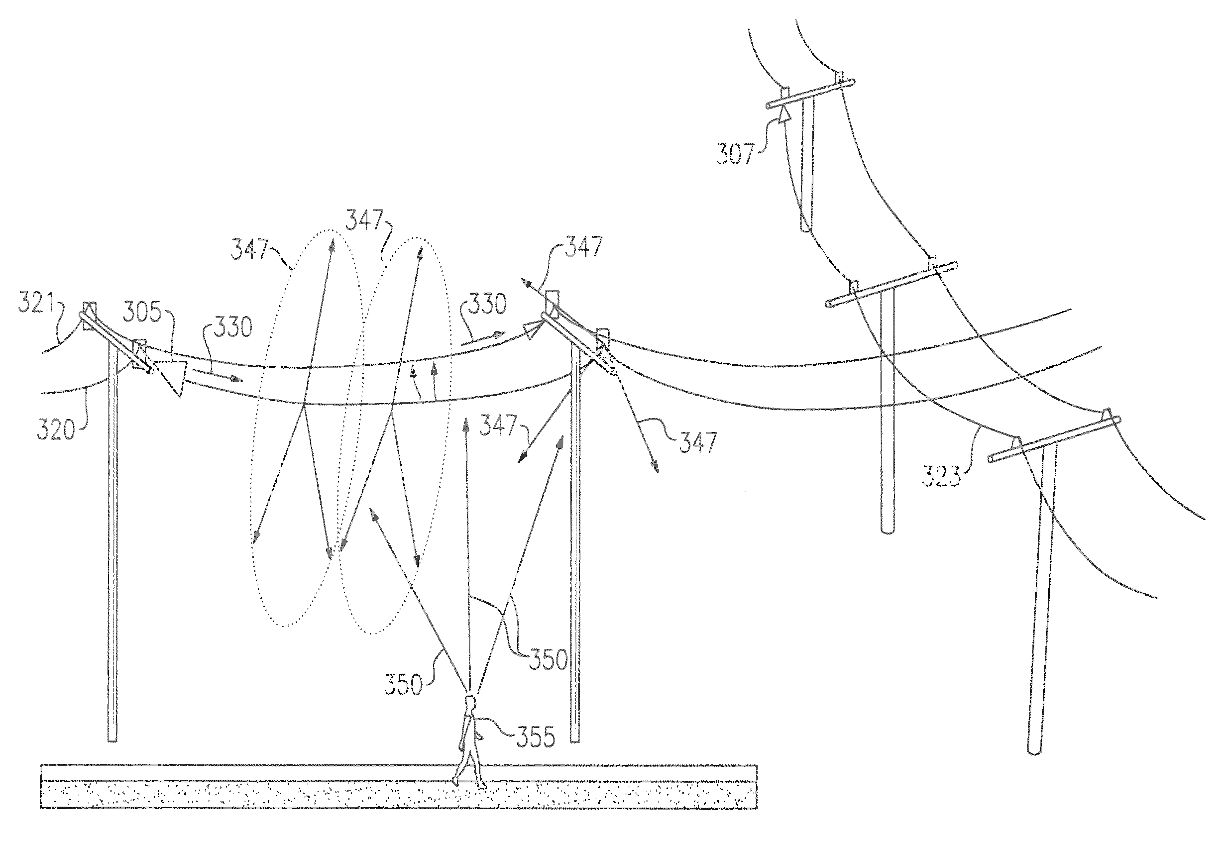
[0240]A bi-static conductive line radar was tested using a set of parallel 2 conductor ACSR-2 (Sparrow) unpowered lines that are 450 feet in length and are at an angle to an access road as shown in FIG. 30. A first surface signal wave launcher 205 was attached at one end of the first unpowered line and a second surface signal wave launcher 206 was connected at the opposite end of the second unpowered line 220.

[0241]For the initial testing, a low-phase noise RF generator was connected to the first surface signal wave launcher 205 and a real-time spectrum analyzer was connected to the second surface signal wave launcher 206 which acted as a receiver. Multiple targets were monitored while transiting the access road near the bi-static conductive line radar. As shown in FIG. 31, persons walking and jogging and vehicles transiting along the access road were detected by the bi-static conductive line radar.


PUM


Abstract

A conductive line radar comprising at least one signal surface wave launcher, which comprises a signal surface wave transceiver, which is physically attached to a power line. The signal surface wave transceiver transmits a wave signal along the power line with another signal radiating from the wave signal in a plurality of directions along the power line. The at least one signal surface wave transceiver receives reflected signals from a target within a distance of the power line. The at least one signal surface wave launcher includes at least one RF communications transceiver and can be inductively powered from the power line.

Description

U.S. GOVERNMENT RIGHTS[0001]This invention was made with United States Government support under N00174-04-D-4143-FG01 TI 045 awarded by the Naval EOD Technical Division. The United States Government has certain rights in the invention.FIELD OF THE INVENTION[0002]The present invention relates to communications systems and methods. In some aspects, the present invention relates to a communications system capable of transmitting a signal over long distances and to radar systems for detecting intrusions along a defined area, such as a perimeter or boundary.BACKGROUND OF THE INVENTION[0003]Modern communications systems and radar systems are increasingly complex and expensive to develop and field. The signals generated, by communications systems and radar systems are propagated into free space where the signal is attenuated by the free space environment as well as encountering interference from other free space radiated signals. The attenuation and interference cause a loss in distance th...

Claims


Application Information

Patent Timeline
Patent Type & Authority Patents(United States)
IPC IPC(8): G01S13/00
CPCG01S13/04G01S13/32G01S13/86G01S13/87
Inventor FARNETH, MIKEMCMAHON, STEPHEN E.ROUGAS, JOHN A.VALOVAGE, EDWARD M.EDWARD, BRIAN
Owner SENSIS CORPORATION
Why Eureka
Try Eureka