Apparatus, method, and system for grounding support structures using an integrated grounding electrode

a grounding electrode and integrated technology, applied in the direction of connection contact material, cable termination, connection device connection, etc., can solve the problems of limited effect of earth grounding electrodes for outdoor light poles as well as other structures, and achieve the effect of reducing installation errors and increasing overall ease of installation

Active Publication Date: 2012-04-24
MUSCO
View PDF10 Cites 17 Cited by
  • Summary
  • Abstract
  • Description
  • Claims
  • Application Information

AI Technical Summary

Benefits of technology

[0008]The effectiveness of earth grounding electrodes for outdoor light poles as well as other structures which may be exposed to lightning or other adverse electrical effects, and may require a low impedance path to ground, is limited, at least in part, by the soil conductivity and installation factors. While the NEC, NFPA, UL and other entities make provisions to standardize and ensure effective earth ground electrode systems, these provisions continue to rely on the onsite contractor to shoulder the labor and material cost associated with earth grounding, as well as ensure the proper installation. Therefore, it is useful to develop means and methods of earth grounding such that installation error is reduced while a low impedance path to ground is maintained. It is further useful for said means and methods to be integral to the outdoor light pole or other structure such that consistency is maintained from application to application and overall ease of installation is increased.
[0012]a. an increased ease of installation when compared to current art grounding systems,
[0013]b. a reduction of onsite installation error when compared to current art grounding systems,
[0016]e. flexibility to provide varying levels of reduced impedance while not preventing grounding according to current art practices.
[0017]One aspect of the present invention, illustrated by one example in FIG. 8, comprises an earth grounding system whereby an earth ground electrode 30 is wound around a pre-cast concrete base 10, fed through an above-backfill access panel 12 in concrete base 10, and run along a portion of the length of a conductive light pole 20 to where electrode 30 is terminated at a termination point 14. When concrete base 10 is placed to depth in the ground, concrete backfill 40 completely surrounds earth ground electrode 30, increasing the surface area in contact with the soil and thereby acting to further reduce impedance. A low impedance path to ground is completed by the following: an adverse electrical condition (e.g., lightning strike) occurs at conductive pole 20, travels to termination point 14, down electrode 30, into concrete backfill 40, and dissipates into the earth. Winding of earth ground electrode 30 in such a fashion allows the minimum earth ground electrode length to be achieved even if the length of concrete base 10 buried in concrete backfill 40 is less than the required length per the aforementioned governing codes.
[0018]Another aspect of the present invention, illustrated by one example in FIGS. 9A and 9B, comprises an earth grounding system whereby a lower earth ground electrode portion 31 (shown as at least two rods to achieve the minimum length per aforementioned governing codes) is attached to concrete base 10. Each rod of lower earth ground electrode 31 is connected to an upper earth ground electrode portion 32 at a connection point 61. Upper earth ground electrode 32 is fed through an above-backfill access panel 12 in concrete base 10, and run along a portion of the length of conductive light pole 20 to where electrode portion 32 is terminated at a termination point 14. When concrete base 10 is placed to depth in the ground, concrete backfill 40 completely surrounds the earth ground electrode 30, increasing the surface area in contact with the soil and further reducing impedance. A low impedance path to ground is completed by the following: an adverse electrical condition (e.g., lightning strike) occurs at conductive pole 20, travels to termination point 14, down electrode portion 32, across connection point 61, down electrode potions 31, into concrete backfill 40, and dissipates into the earth. Connecting lower earth ground electrode portion 31 to concrete base 10 during manufacturing eliminates the need for the contractor to separately drive earth ground electrodes into the ground onsite, but the availability of access panel 12 still allows for a contractor to do so and wire the driven electrodes to termination point 14 or integrate with electrode portion 32, if desired. Connection point(s) 61 may also be completed during manufacturing to further reduce installation error and improve the overall ease of installation.

Problems solved by technology

The effectiveness of earth grounding electrodes for outdoor light poles as well as other structures which may be exposed to lightning or other adverse electrical effects, and may require a low impedance path to ground, is limited, at least in part, by the soil conductivity and installation factors.

Method used


Image

  • Apparatus, method, and system for grounding support structures using an integrated grounding electrode
  • Apparatus, method, and system for grounding support structures using an integrated grounding electrode
  • Apparatus, method, and system for grounding support structures using an integrated grounding electrode

Examples


embodiment 1

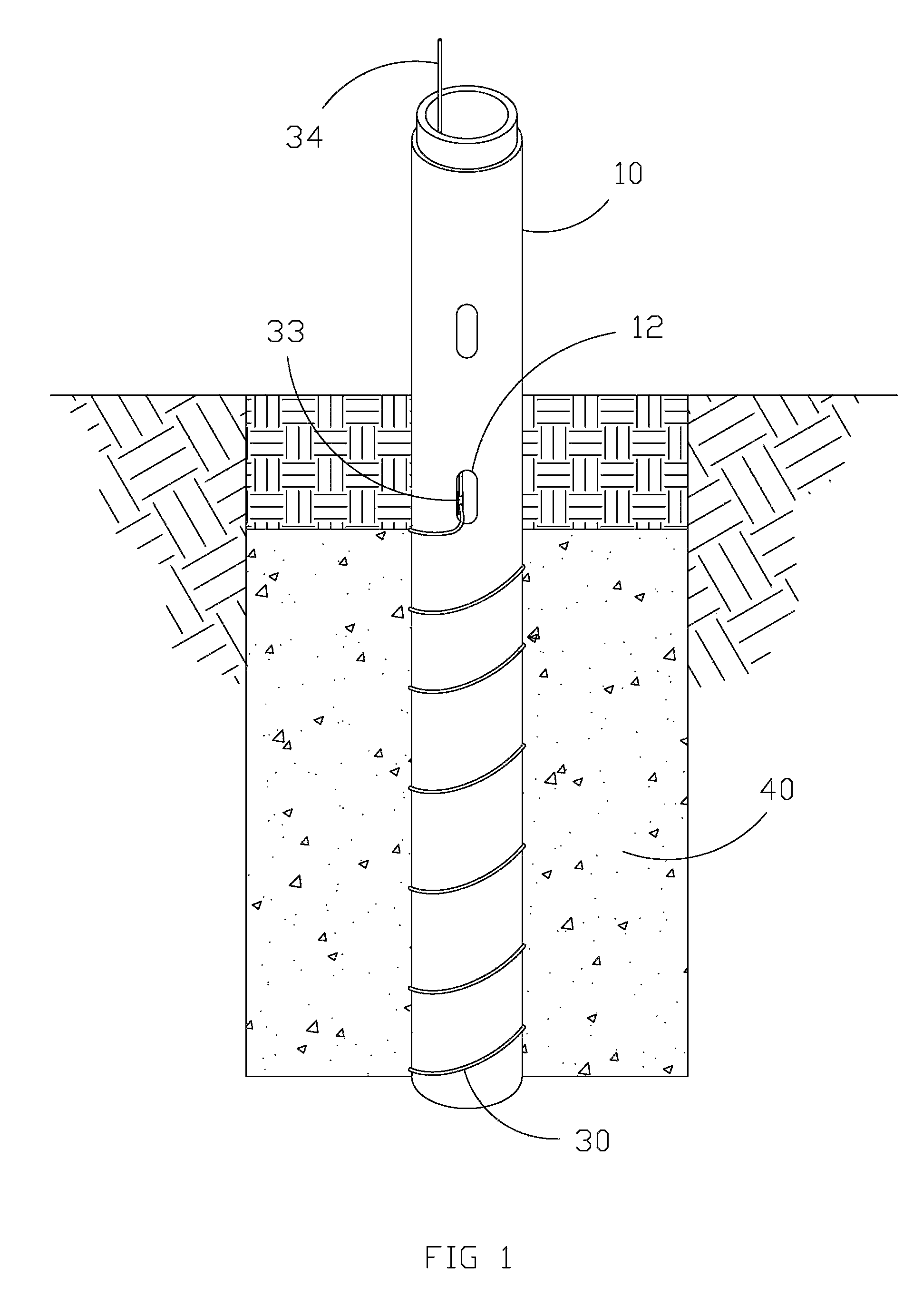
[0042]B. Exemplary Method and Apparatus FIG. 1

[0043]Earth ground electrode portion 30 is wound around pre-cast concrete base 10 and fed through an above-backfill access panel 12 where it terminates at an electrical junction 33; base 10 may be as is described in U.S. Pat. No. 5,398,478, incorporated herein by reference. Earth ground electrode portion 34 is connected to electrode portion 30 at junction 33. Junction 33 may comprise any manner of conductive fastening device (preferably one that is UL listed) and may further comprise a layer of corrosion protection. Earth ground electrode portion 34 runs along the inner diameter of the upper portion of base 10, extends above base 10, and attaches to the light pole (not shown).

[0044]The path to ground is completed by the following: connection made at the light pole (not shown), along earth ground electrode portion 34, across junction 33, along earth ground electrode portion 30, and dissipated into backfilled concrete 40. Alternatively, el...

embodiment 2

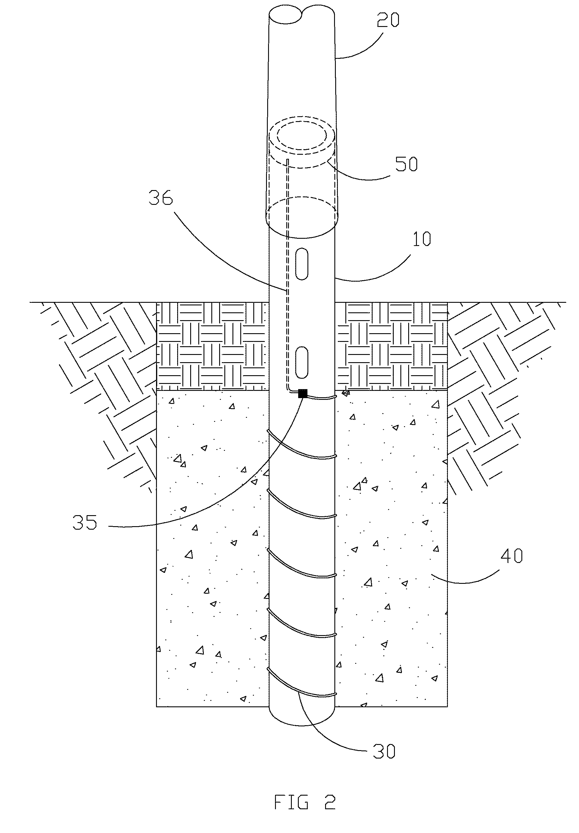
[0047]C. Exemplary Method and Apparatus FIG. 2

[0048]Earth ground electrode portion 30 is wound around pre-cast concrete base 10 and fed through the thickness of concrete base 10 at a connection point 35. Earth ground electrode portion 36 is connected to earth ground electrode portion 30 via connection point 35. Connection point 35 may comprise any means and methods of bonding two conductive materials (e.g., weld joint) and may further comprise a corrosion protection layer; alternatively, connection point may utilize an apparatus for joining two conductive materials such as bolt assembly 100 illustrated in FIGS. 12A and B. Earth ground electrode portion 36 is cast inside the wall of concrete base 10 and runs the remaining length of base 10 where it terminates at a conductive collar 50 which is in direct contact with a conductive light pole 20. Electrode portion 30 and lower part of base 10 is then encased in backfilled concrete 40. As illustrated, the outside diameter of collar 50 ma...

embodiment 3

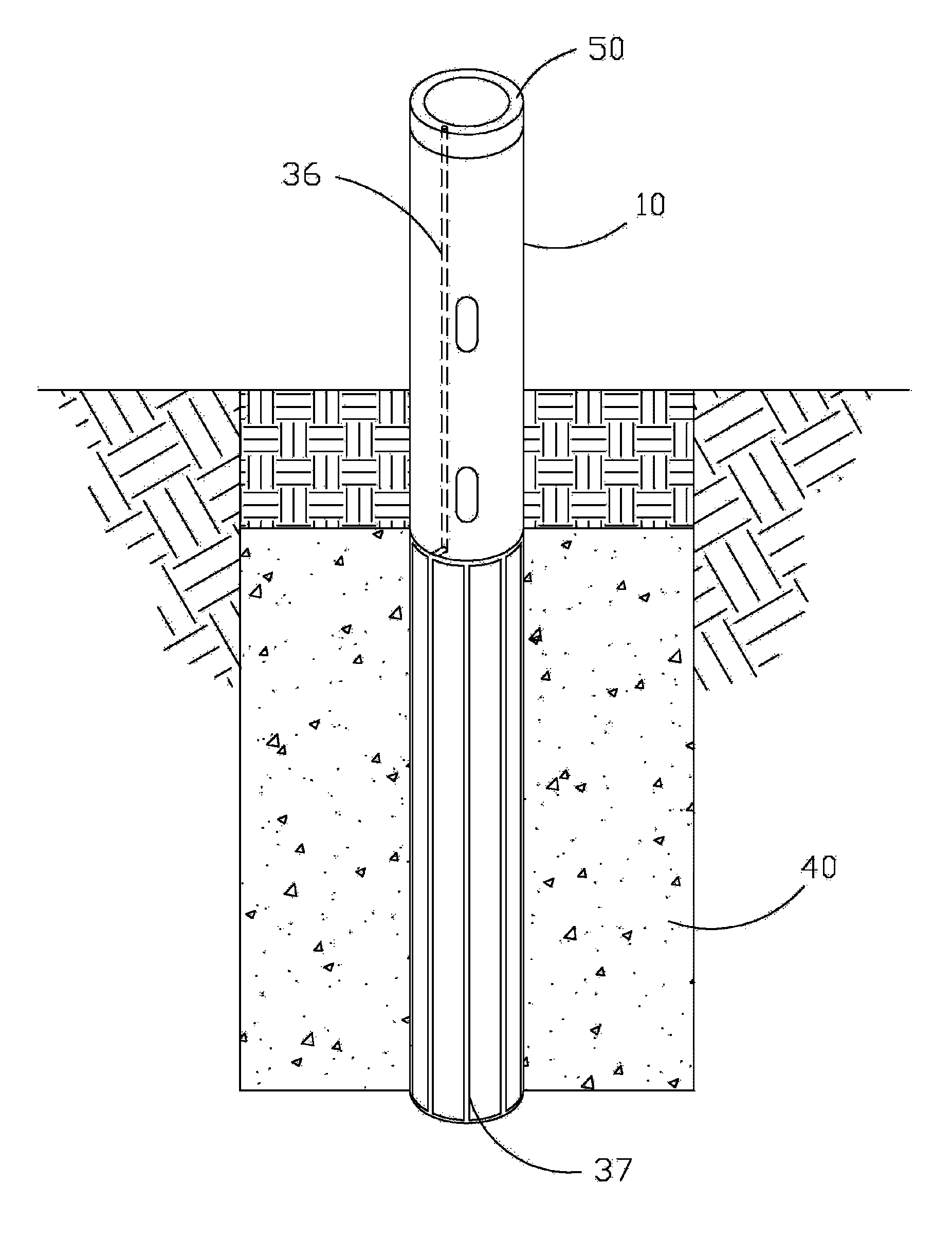
[0053]D. Exemplary Method and Apparatus FIG. 3

[0054]An earth ground electrode portion 37 comprises a conductive cage embedded in the surface of pre-cast concrete base 10. Conductive cage 37 is in contact with earth ground electrode portion 36 which is cast inside the wall of concrete base 10. Earth ground electrode portion 36 runs the length of the upper portion of base 10 where it terminates at conductive collar 50 which is in direct contact with the conductive light pole (not shown). Electrode cage portion 37 is then encased in backfilled concrete 40.

[0055]The path to ground is completed by the following: the light pole (not shown), across conductive collar 50, along earth ground electrode portion 36, along earth ground electrode cage portion 37, and dissipated into the backfilled concrete 40.

[0056]Alternatively, earth grounding electrode portion 36 may continue through collar 50 to an electrical termination point on the conductive light pole (not shown) similar to Exemplary Metho...


PUM

PropertyMeasurementUnit
depthaaaaaaaaaa
lengthaaaaaaaaaa
resistanceaaaaaaaaaa

Abstract

Disclosed herein are apparatus, methods, and systems for grounding outdoor light poles, as well as other structures, which may be exposed to lightning or other adverse electrical effects and may require a low impedance path to ground. Inventive aspects include a combination of apparatus integral to the pole or other structure and installation considerations whereby the ease of installation, reduction of onsite installation error, and reduction of impedance may be tailored to each installation. An apparatus can include a pre-installed earth grounding electrode at the lower end of the pole or structure to be inserted into the earth. A method can include installing an earth grounding electrode to / on / in a lower end of a pole or structure prior to insertion into the earth.

Description

CROSS-REFERENCE TO RELATED APPLICATIONS[0001]This application claims priority under 35 U.S.C. §119 to provisional U.S. application Ser. No. 61 / 157,017, filed Mar. 3, 2009, hereby incorporated by reference in its entirety.I. BACKGROUND OF THE INVENTION[0002]The present invention generally relates to grounding structures which may experience adverse electrical effects, such as lightning. More specifically, the present invention relates to grounding outdoor support structures, such as light poles, by providing a low impedance path to ground.[0003]It is well known that earth grounding is required for outdoor light poles as well as other structures per the United States National Electric Code (NEC), National Fire Prevention Association (NFPA), and most local codes. The general purpose of earth grounding such structures is to provide a path of low impedance such that electrical discharge from lightning or other sources may be dissipated to the earth with minimal damage to property or pers...

Claims


Application Information

Patent Timeline
Patent Type & Authority Patents(United States)
IPC IPC(8): H01R4/66
CPCH01R4/66Y10T29/49117Y10T29/49002
Inventor GORDIN, MYRONBARKER, DAVID L.GROMOTKA, GABRIEL P.KUBBE, GREGORY N.
Owner MUSCO
Why Eureka
Try Eureka