Structure of trench capacitor and method for manufacturing the same

a technology of trench capacitors and structures, applied in the direction of semiconductor devices, electrical equipment, transistors, etc., can solve the problems of deterioration of the quality of deposited electrodes, current leakage problems of trench capacitors, inaccurate failure analysis,

Active Publication Date: 2012-04-24
UNITED MICROELECTRONICS CORP
View PDF7 Cites 0 Cited by
  • Summary
  • Abstract
  • Description
  • Claims
  • Application Information

AI Technical Summary

Benefits of technology

[0010]It is therefore a primary objective of the claimed invention to provide a trench capacitor and a method to solve the over-etching or insufficient etching problem of the collar oxide layer, and to improve the accuracy of the failure analysis.
[0014]Unlike the conventional method, the collar oxide layer in the present invention is formed by the thermal oxidation process. Moreover, a protective layer and a mask layer cover the collar oxide layer. During the second trench formation, the mask layer serves as a mask. Therefore, the over-etching or insufficient etching problem of the collar oxide layer can be avoided. Furthermore, the protective layer can be utilized as an indicating material to determine if the collar oxide layer is at a suitable thickness.

Problems solved by technology

Therefore, the trench capacitor will have a current leakage problem.
Furthermore, the quality of the deposited electrode will also be deteriorated.
Moreover, during a failure analysis process, the conventional detecting machine has a problem in determining the thickness of the collar oxide layer 32, which leads to an inaccurate failure analysis.

Method used


Image

  • Structure of trench capacitor and method for manufacturing the same
  • Structure of trench capacitor and method for manufacturing the same
  • Structure of trench capacitor and method for manufacturing the same

Examples


Embodiment Construction

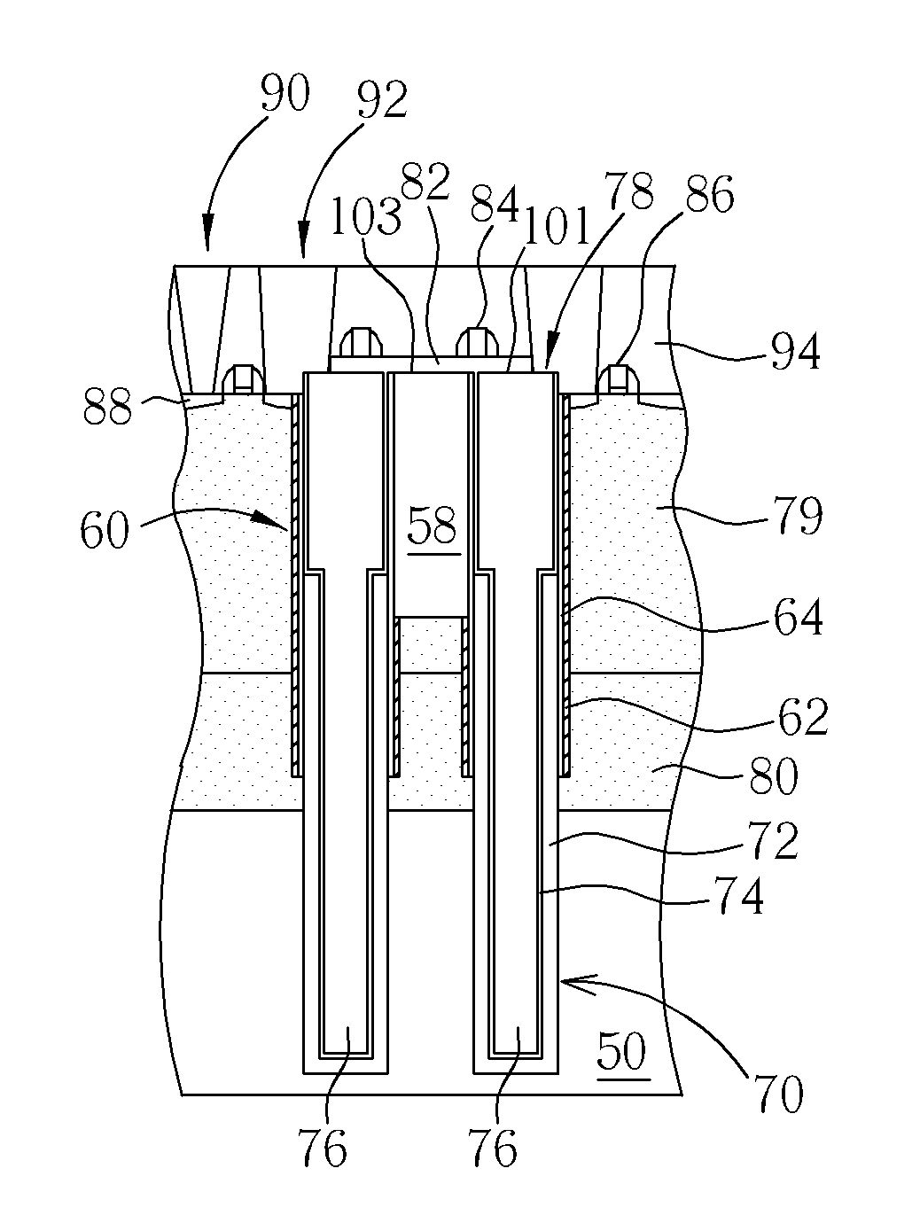
[0018]FIG. 6 to FIG. 11 are schematic diagrams illustrating a fabricating method of a trench capacitor of the present invention. As shown in FIG. 6, a substrate such as a semi-conductive substrate 50 is provided. The semi-conductive substrate 50 is covered by a pad silicon nitride 52, a buffering silicon nitride layer 54 and a plasma enhanced oxide (PEOX) layer 56. In addition, the semi-conductive substrate 50 has an STI 58. The STI 58 is formed in the semi-conductive substrate 50, the pad silicon nitride 52 and the buffering silicon nitride layer 54 by the conventional STI formation process. Then, a patterned photoresist (not shown) is taken as a mask to partly etch the PEOX layer 56, the buffering silicon nitride layer 54, the STI, the pad silicon nitride 52 and the semi-conductive substrate 50. In this way, a first trench 60 is formed at two sides of the STI 58.

[0019]As shown in FIG. 7, a thermal process such as a rapid thermal oxidation process or an in-situ steam generation pro...


PUM


Abstract

A structure of trench capacitor and method for manufacturing the trench capacitor is provided. The collar oxide layer of the trench capacitor is formed by a thermal oxidation process. Moreover, a protective layer such as silicon nitride covers the collar oxide layer. A failure analysis of the collar oxide layer can be operated by detecting the protective layer. If the protective layer is detected, the collar oxide layer is therefore at a suitable thickness. Furthermore, a mask layer rather than the collar oxide layer is used as a mask during the trench formation.

Description

BACKGROUND OF THE INVENTION[0001]1. Field of the Invention[0002]The invention relates to a structure of a trench capacitor and method for manufacturing the same, and more particularly, to a method of manufacturing a trench capacitor with a protective layer covering on the collar oxide layer. In this way, the reliability of a failure analysis can be improved.[0003]2. Description of the Prior Art[0004]As electrical products tend towards increasing miniaturization, DRAM devices need to have a high integration and density. Trench capacitor DRAM devices are popularly used as high density DRAMs formed in a deep trench capacitor of the semiconductor substrate to effectively decrease the size of the memory unit and efficiently utilize the space of the chip.[0005]Please refer to FIG. 1 to FIG. 5, which are schematic cross-sectional views showing the fabrication of the trench capacitor according to the prior art.[0006]As shown in FIG. 1, a substrate 10 having a STI 12, a pad silicon nitride 1...

Claims


Application Information

Patent Timeline
Patent Type & Authority Patents(United States)
IPC IPC(8): H01L21/02
CPCH01L27/10861H01L29/66181H01L27/10829H10B12/37H10B12/038
Inventor SU, YI-NANCHANG, CHUN-MING
Owner UNITED MICROELECTRONICS CORP
Why Eureka
Try Eureka