Excimer lamps

a technology of excimer lamps and lampshades, which is applied in the direction of instruments, discharge tubes, luminescnet screens, etc., can solve the problems of uneven illumination in the axial direction of the discharge vessel, and achieve the effect of efficient reflection and diffusion

Active Publication Date: 2012-04-24
USHIO DENKI KK
View PDF31 Cites 3 Cited by
  • Summary
  • Abstract
  • Description
  • Claims
  • Application Information

AI Technical Summary

Benefits of technology

[0010]The present invention was devised in view of the aforementioned circumstances. Thus, a primary object of the present invention is to provide excimer lamps that allow a reduction in the extent to which the reflectivity of an ultraviolet reflection film decreases as a result of being operated for an extended period of time and which provides a uniform illuminance in the axial direction of the discharge vessel.
[0013]In the excimer lamp according to the present invention, particle boundaries do not disappear by lighting for an extended period of time because an ultraviolet reflection film is constituted of silica particles and alumina particles, and the silica particles have a specified mean particle diameter relative to the mean particle diameter of the alumina particles. Vacuum ultraviolet radiation can therefore be reflected and diffused efficiently while maintaining the initial reflectivity, and mass difference between the silica particles and the alumina particles caused by a difference in specific gravity can be maintained within a specified range, which allows equalizing the flow properties of the silica particles and alumina particles in a liquid dispersion prepared at the time of forming an ultraviolet reflection film. As a result, the silica particles and alumina particles are evenly dispersed in the ultraviolet reflection film, which allows a uniform illuminance in the axial direction of the discharge vessel to be achieved.

Problems solved by technology

However, it was found that there was a problem in excimer lamps equipped with the aforementioned ultraviolet reflection film that the illuminance becomes uneven in the axial direction of the discharge vessel.

Method used


Image

  • Excimer lamps
  • Excimer lamps
  • Excimer lamps

Examples


Embodiment Construction

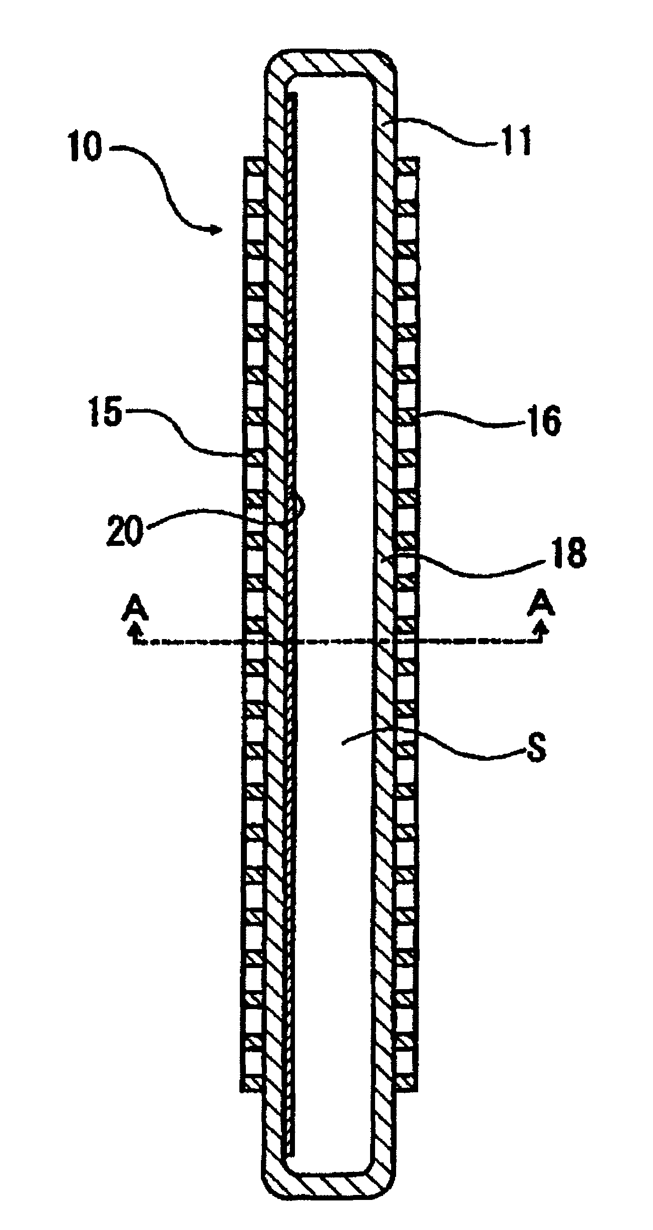
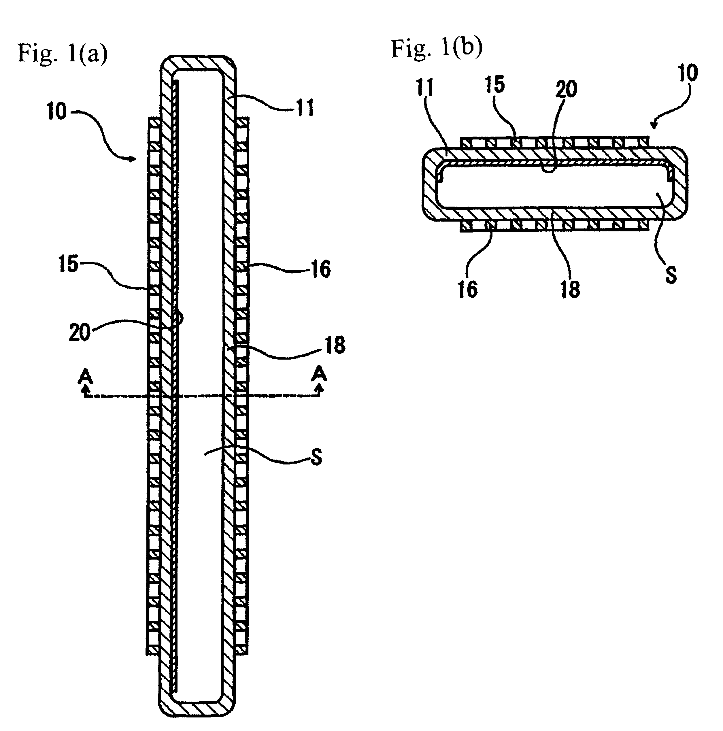
[0019]FIGS. 1(a) &1(b) are sectional views showing the schematic configuration of an excimer lamp 10 according to an embodiment of the present invention with FIG. 1(a) being a cross-sectional view along the longitudinal direction of a discharge vessel and FIG. 1(b) being a sectional view taken along line A-A line of FIG. 1(a).

[0020]Excimer lamp 10 comprises a long and hollow discharge vessel 11 whose cross section is rectangular. Both ends of the discharge vessel 11 are hermetically sealed so that an airtight discharge space is formed inside. The discharge space of the discharge vessel 11 is filled with a discharge gas, such as xenon gas or a mixture of argon and chlorine.

[0021]The discharge vessel 11 is made of silica glass (e.g., synthetic quartz glass) that allows the passage of vacuum ultraviolet radiation well and functions as a dielectric.

[0022]On the outer surface of the discharge vessel 11 on the long side is provided a pair of electrodes (i.e., an electrode 15, which functi...


PUM


Abstract

To avoid a decline in the reflectivity of an ultraviolet reflection film caused by lighting for an extended period of time and providing a uniform illuminance an excimer lamp has a silica glass discharge vessel with electrodes on opposite sides of the discharge vessel, wherein excimer discharge is generated in the discharge space of the discharge vessel, wherein an ultraviolet reflection film made of silica particles and alumina particles is formed on a surface exposed to the discharge space and wherein the mean particle diameter of silica particles is at least 0.67 times as large as the mean particle diameter of the alumina particles. The alumina particles in the ultraviolet reflection film preferably constitute at least 5 wt % and more preferably at least 10 wt % of the sum of silica particles and alumina particles.

Description

BACKGROUND OF THE INVENTION[0001]1. Field of Invention[0002]The present invention relates to an excimer lamp comprising a discharge vessel made of silica glass having a discharge space, wherein a pair of electrodes is provided on both sides of the silica glass vessel and wherein excimer discharge is generated inside the discharge vessel.[0003]2. Description of Related Art[0004]Various technologies have been developed and put into practical use recently for treating an article made of metal, glass or other materials by means of the action of vacuum ultraviolet radiation with a wavelength of at most 200 nm and ozone generated thereby by radiating the vacuum ultraviolet radiation onto the article to be treated, which includes a cleaning treatment technology for removing organic impurities adhering to the surface of the article and an oxide film formation treatment technology for forming an oxide film on the surface of the article to be treated.[0005]As an example, a device for emitting...

Claims


Application Information

Patent Timeline
Patent Type & Authority Patents(United States)
IPC IPC(8): H01J5/16H01J61/40H01K1/26H01K1/30
CPCH01J61/35H01J65/00
Inventor FUJISAWA, SHIGEKIMORIMOTO, YUKIHIRO
Owner USHIO DENKI KK
Why Eureka
Try Eureka