Endoscope and objective lens for the same

a technology of endoscope and objective lens, which is applied in the field of endoscope, can solve the problems of deteriorating image quality, increasing the change of optical performance with respect to a manufacturing error, and not changing the manufacturing error caused during the processing of optical lenses, etc., and achieves the effect of wide angle of view and small siz

Active Publication Date: 2012-04-24
HOYA CORP
View PDF9 Cites 8 Cited by
  • Summary
  • Abstract
  • Description
  • Claims
  • Application Information

AI Technical Summary

Benefits of technology

[0007]The present invention is advantageous in that it provides an objective lens for an endoscope configured to suitably suppress change of an angle of view and change of curvature of field due to a manufacturing error and an assembling error while having a small size and having a wide angle of view, and provides an endoscope on which the objective lens is installed.
[0010]With this configuration, it becomes possible to provide an objective lens for an endoscope configured to suitably suppress change of an angle of view and change of curvature of field due to a manufacturing error and an assembling error while having a small size and having a wide angle of view, and provides an endoscope in which the objective lens is installed.
[0012]When fF / f gets smaller than the lower limit of the condition (1), change of magnification of the rear lens group due to change of the interval between the front-side positive lens and the rear-side positive lens can be suppressed, and therefore the change of the angle of view becomes small. However, in this case, it becomes necessary to set the magnification of the front lens group to be large, and thereby it becomes impossible to suppress the deviated curvature of field caused by a positional error of installation of the front lens group.
[0018]When fFP / fF gets smaller than the lower limit of the condition (3), an excessively large power is assigned to the front-side negative lens, and therefore the deviated curvature of field due to a positional error of installation of the front lens group becomes large. Furthermore, as a result of reduction of the power of the front-side positive lens, it becomes necessary to increase the magnification of the rear lens group. In this case, the focal length f of the entire optical system tends to easily change depending on the change of the interval between the front-side positive lens and the rear-side positive lens. That is, change of the angle of view becomes large.

Problems solved by technology

However, in general, an optical lens shows a property that a curvature of field increases in proportion to the square of the angle of view, and thereby the image quality is deteriorated.
Incidentally, in principle, a manufacturing error caused during processing of optical lenses does not vary even if optical lenses vary in design size.
Therefore, change of the optical performance with respect to a manufacturing error becomes more noticeable as the size of the optical lens becomes small.
Similarly, change of the optical performance due to an assembling error becomes more noticeable as the size of an optical unit becomes small.
The fact that the objective lens of the endoscope needs to decrease the number of lenses and thereby to increase a power to be assigned to each lens of the objective lens also badly affects the above described change of the optical performance.
Regarding a small size and wide angle of view objective lens for an endoscope, change of the angle of view and change of the curvature of field due to a manufacturing error and an assembling error are seen as problems.
However, in this case, a problem arises that the yield decreases and the manufacturing unit price increases.
In addition, regarding a small size optical lens, grasping and managing the occurred error amounts are technically difficult.
Therefore, strict management of manufacturing tolerances can not be employed.
However, according to the configurations of the objective lenses disclosed in the publications, change of the angle of view and change of the curvature of field due to a manufacturing error and an assembling error are not suppressed sufficiently, and in actuality it is difficult to achieve the suitable optical performance if strict management of manufacturing tolerances is not conducted.

Method used


Image

  • Endoscope and objective lens for the same
  • Endoscope and objective lens for the same
  • Endoscope and objective lens for the same

Examples


first example

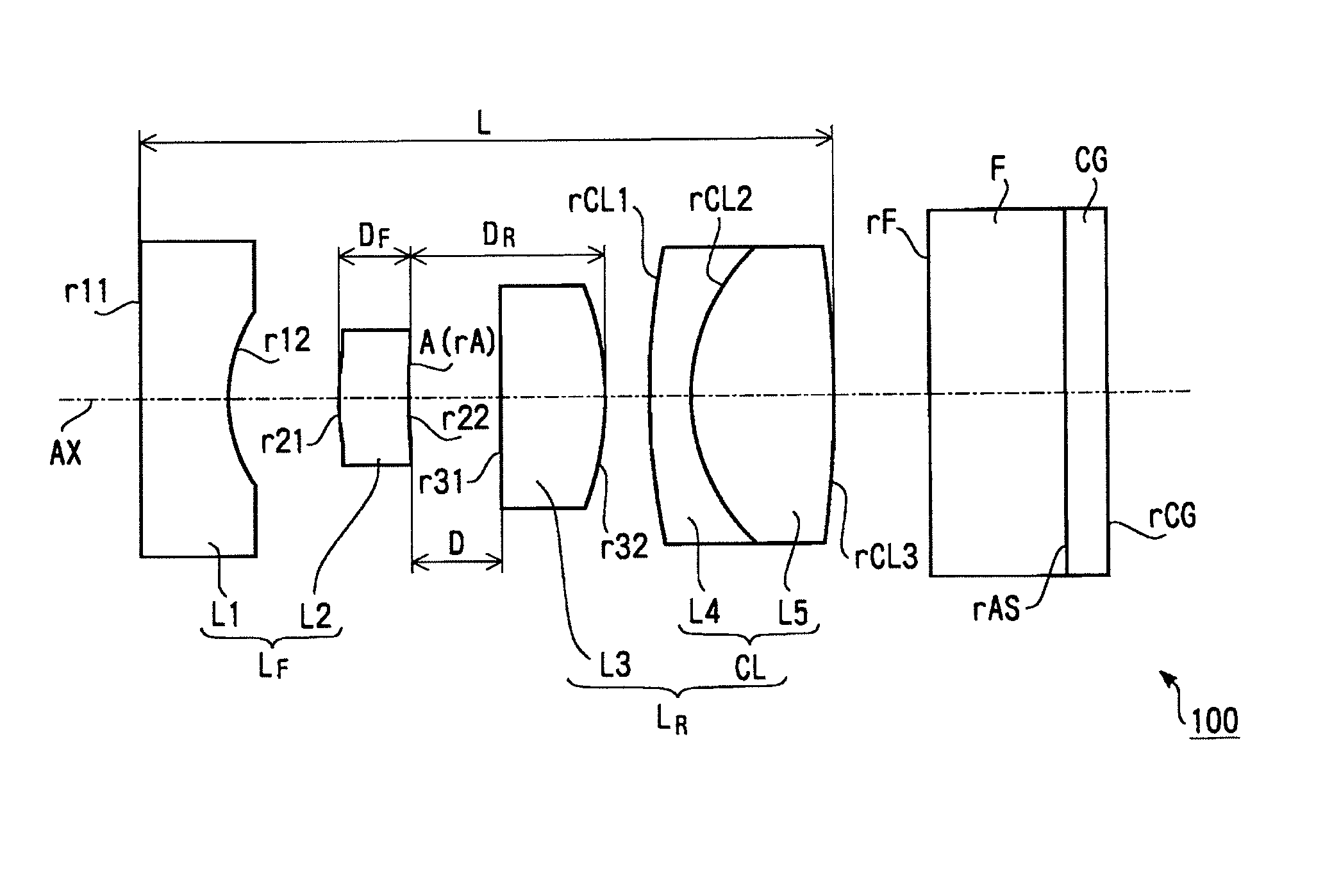
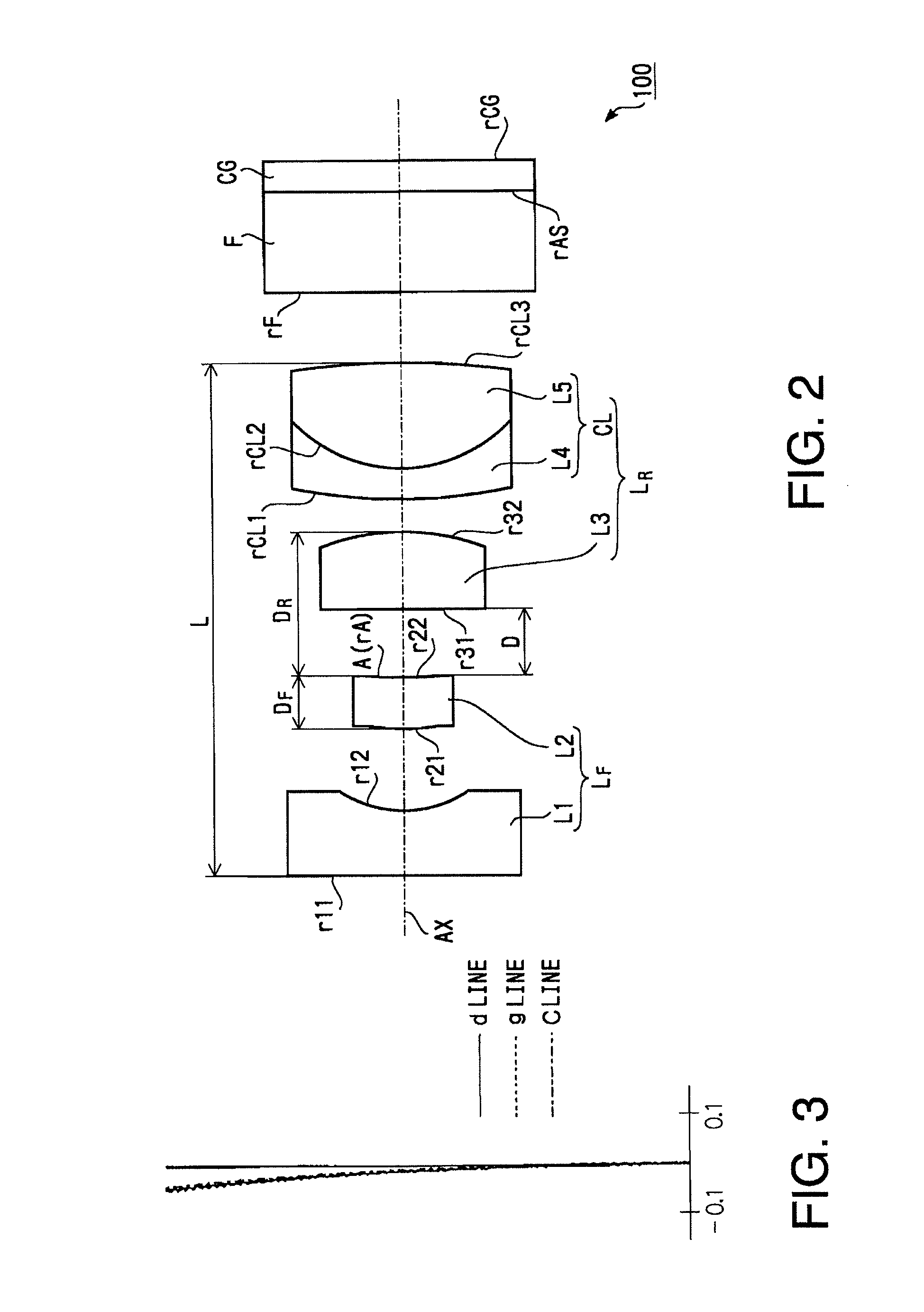
[0103]As described above, FIG. 2 shows the configuration of the objective lens 100 according to a first example of the invention. Table 1 shows a concrete numerical configuration (design values) of the objective lens 100 according to the first example and the optical components arranged on the rear side of the objective lens 100. In Table 1 (and in the following similar tables), r (unit: mm) denotes an curvature radius of a surface of each optical component, d (unit: mm) denotes the thickness of an optical component or the distance (unit: mm) from each optical surface to the next optical surface, “Nd” denotes a refractive index at a d-line (a wavelength of 588 nm), and vd denotes Abbe number at the d-line. “r” of an aspherical element is a curvature radius defined on the optical axis AX. In Table 1, the surfaces #1 and #2 respectively denote the first surface r11 and the second surface r22 of the negative lens L1, surfaces #3 and #4 respectively denote the first surface r21 and the ...

second example

[0110]Hereafter, a second example of the invention is explained. FIG. 7 is a side view illustrating a configuration of the objective lens 100 according to the second example and the optical components arranged on the rear side of the objective lens 100. Table 3 shows the concrete numerical configuration (design values) of the objective lens 100 according to the second example and the optical components arranged on the rear side of the objective lens 100. Table 4 shows the coefficients (design values) defining aspherical surfaces of the first surface r21 of the positive lens L2 and the second surface r32 of the positive lens L3.

[0111]ω: 70.0

[0112]y: 1.05

[0113]

TABLE 3Surface No.rdNdνd1∞0.5201.8830040.820.8860.613——31.8900.5061.8640040.64∞0.000——5∞0.065——6−2.7371.0721.8640040.67−1.2360.570——87.4340.2481.9228618.991.2680.8921.7725049.610−3.6870.606——11∞0.8251.5163364.212∞0.2481.5100064.113∞———

[0114]

TABLE 4Surface No.κA4A6A830.000−0.8855E−020.2226E+01−0.1025E+0270.0000.4491E−01−0.1476E+0...

third example

[0116]Hereafter, a third example of the invention is explained. FIG. 12 is a side view illustrating a configuration of the objective lens 100 according to the third example and the optical components arranged on the rear side of the objective lens 100. Table 5 shows the concrete numerical configuration (design values) of the objective lens 100 according to the third example and the optical components arranged on the rear side of the objective lens 100. Table 6 shows the coefficients (design values) defining aspherical surfaces of the first surface r21 of the positive lens L2 and the second surface r32 of the positive lens L3.

[0117]ω: 73.3

[0118]y: 1.08

[0119]

TABLE 5Surface No.rdNdνd1∞0.5191.8830040.820.8690.687——32.4750.4331.8640040.64∞0.000——5∞0.534——6∞0.6341.8640040.67−1.6960.349——85.6070.4121.9228618.991.2190.9371.7725049.610−4.7030.646——11∞0.8241.5163364.212∞0.2471.5100064.113∞———

[0120]

TABLE 6Surface No.κA4A6A830.0000.1191E+000.1782E+000.0000E+0070.0000.4808E−01-0.4831E−010.3964E−...


PUM


Abstract

An objective lens for an endoscope, including a negative front lens group and a positive rear lens group arranged such that an aperture stop is positioned therebetween, wherein the front lens group has at least a front-side negative lens and a front-side positive lens arranged in this order from an object side, and the rear lens group has at least a rear-side positive lens and a cemented lens arranged in this order from the object side, the cemented lens being configured by cementing together negative and positive lenses. The objective lens satisfies following conditions: −4.5≦fF / f≦−2.0 and 1.5≦fRP / f≦2.5, where fF (unit: mm) represent of the front lens group, f (unit: mm) represents a total focal length of the front lens group and the rear lens group, and fRP (unit: mm) represents a focal length of the rear-side positive lens.

Description

BACKGROUND OF THE INVENTION[0001]The present invention relates to an endoscope used when a doctor conducts diagnosis on an body cavity and an objective lens for an endoscope arranged in a tip portion of the endoscope. In particular, the present invention relates to an objective lens for an endoscope configured such that change of an angle of view and change of curvature of field due to a manufacturing error and an assembling error are suppressed suitably, and to an endoscope on which such an objective lens is installed.[0002]Medical endoscopes, such as a fiber scope or an electronic endoscope, are widely used by doctors for medical diagnosis for a body cavity of a patient. A tip part of an endoscope of this type is designed to be compact in size so that an insertion unit thereof can be smoothly inserted into a small space, such as a body cavity of a patient. In the tip part of the endoscope, various types of components are accommodated. It is understood that the minimum design outer...

Claims


Application Information

Patent Timeline
Patent Type & Authority Patents(United States)
IPC IPC(8): G02B9/34G02B21/02A61B1/06G02B9/08
CPCG02B15/177G02B23/2438
Inventor NASU, SACHIKO
Owner HOYA CORP
Why Eureka
Try Eureka