Process for the production of methanol including one or more membrane separation steps

a technology of methanol and membrane separation, which is applied in the direction of separation process, oxygen-containing compound preparation, oxygen-containing compound purification/separation, etc., can solve the problems of unnecessary costs, and achieve the effect of preventing its release to the environment and reducing the compression requirements of the process

Active Publication Date: 2012-05-01
MEMBRANE TECH & RES
View PDF5 Cites 11 Cited by
  • Summary
  • Abstract
  • Description
  • Claims
  • Application Information

AI Technical Summary

Benefits of technology

[0026]By practicing the process of the invention, compression requirements for the process may be reduced by up to 15% or more. Additionally, the process of the invention may debottleneck existing methanol plants if more syngas or carbon dioxide is available. Debottlenecking the compressor allows feed of imported carbon dioxide into the synthesis loop, resulting in additional methanol production, without the drawbacks of feeding carbon dioxide to the reformer. This is a way of sequestering carbon dioxide, thereby preventing its release to the environment. In addition, the process of the invention generates a hydrogen-rich stream from the membrane separation step. This hydrogen-rich stream can be used for other purposes.

Problems solved by technology

However, due to the rising cost of methanol and its corrosivity to rubber and many synthetic polymers used in the auto industry, by the late 1990's automakers had stopped building vehicles capable of operating on either methanol or gasoline (“flexible fuel vehicles”), switching their attention instead to ethanol-fueled vehicles.
As a result, the methanol production process is inefficient, resulting in unnecessary costs due to increased compressor power requirements and less than optimum methanol yields.

Method used


Image

  • Process for the production of methanol including one or more membrane separation steps
  • Process for the production of methanol including one or more membrane separation steps
  • Process for the production of methanol including one or more membrane separation steps

Examples


example 1

Conventional Methanol Production Process (not in Accordance with the Invention)

[0084]The computer calculations in the following Examples were performed using a modeling program, ChemCad 5.6 (ChemStations, Inc., Houston, Tex.) containing code developed by assignee's engineering group for applications specific to assignee's processes.

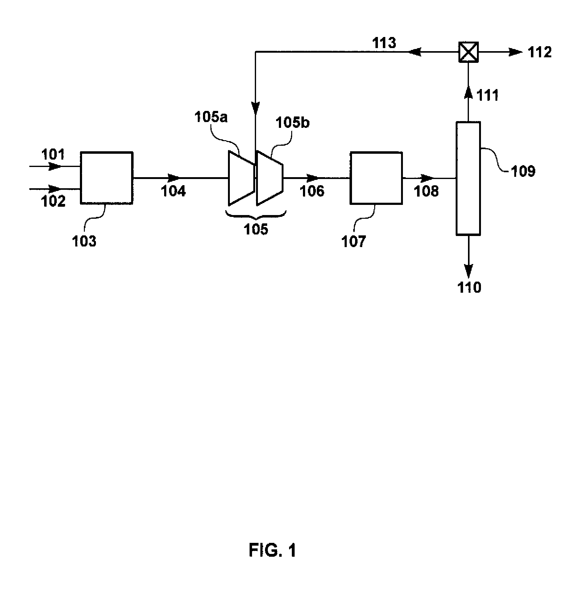
[0085]The calculation for this Example was performed using the flow scheme shown in FIG. 1 and described in the Background of the Invention, above. This flow scheme does not include a membrane separation step upstream of the methanol synthesis process (not in accordance with the invention). Syngas flow was assumed to be 106 metric tons per hour (Mt / h).

[0086]The flow rates and chemical compositions of the streams in the methanol synthesis loop were calculated. The results of this calculation are shown in Table 1.

[0087]

TABLE 1ReactorReactorOverheadRecycleSyngasFeed GasOutputCondensateStreamPurge GasGasParameter / Stream104106108110111112113Total Flow (Mt / h)10...

example 2

Methanol Production Process in Accordance with the Invention

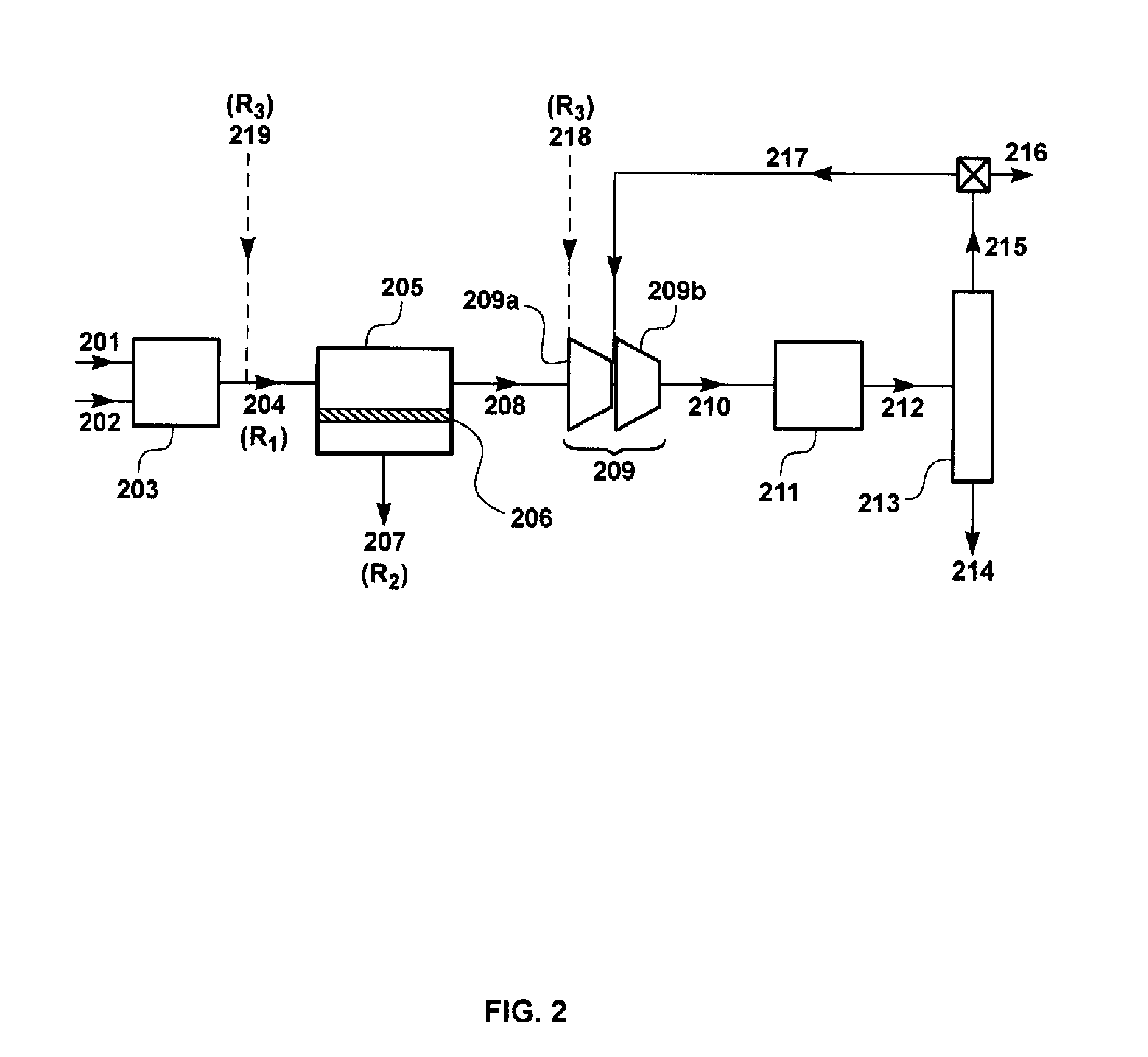
[0089]The calculation for this Example was performed using the flow scheme shown in FIG. 2 and described in the Detailed Description, above. This flow scheme includes a membrane separation step upstream of the methanol synthesis loop.

[0090]The membranes, 206, in membrane separation unit, 205, were assumed to have the properties shown in Table 2, at a membrane operating temperature within the range of about 50° C. and about 150° C.

[0091]

TABLE 2GasPermeance (gpu)*H2 / Gas Selectivity**Hydrogen300—Carbon monoxide>100Carbon dioxide2015Methane>100Nitrogen>100Water5000.6*Gas permeation unit; 1 gpu = 1 × 10⁻⁶ cm3(STP) / cm2 · s · cmHg**Estimated, not measured

[0092]As with Example 1, syngas flow for this calculation was assumed to be 106 Mt / h. The flow rates and chemical compositions of the streams in the methanol synthesis loop were calculated. The results of this calculation are shown in Table 3.

[0093]

TABLE 3ReactorMembraneTreatedFee...

example 3

Methanol Production Loss from Co-Permeation of Carbon Dioxide

[0096]Many hydrogen-permeable membranes show good selectivity for hydrogen over carbon monoxide. However, good selectivity for hydrogen over carbon dioxide is much harder to realize. Because of this, a series of calculations of the type described in FIG. 2 was performed, varying the hydrogen / carbon dioxide selectivity from 3 to 15. The results of the calculations were used to create the curves shown in FIG. 4, which is a plot 400 showing methanol production loss (due to co-permeation of carbon oxides) 401 as a function of membrane hydrogen / carbon dioxide selectivity 402. Curve 403 represents a permeate stream pressure of 4 bar (60 psia); curve 404 represents a permeate stream pressure of 2 bar (30 psia). Feed stream pressure in both cases was 240 psia.

[0097]As can be seen from the figure, at a given membrane selectivity, methanol production loss from co-permeation of carbon oxides is slightly higher at a permeate pressure ...


PUM

PropertyMeasurementUnit
temperatureaaaaaaaaaa
pressureaaaaaaaaaa
pressureaaaaaaaaaa

Abstract

Disclosed herein is a methanol production process that includes a membrane separation step or steps. Using the process of the invention, the efficiency of methanol production from syngas is increased by reducing the compression requirements of the process and / or improving the methanol product yield. As an additional advantage, the membrane separation step generates a hydrogen-rich stream which can be sent for other uses. An additional benefit is that the process of the invention may debottleneck existing methanol plants if more syngas or carbon dioxide is available, allowing for feed of imported carbon dioxide into the synthesis loop. This is a way of sequestering carbon dioxide.

Description

FIELD OF THE INVENTION[0001]The invention relates to a methanol production process that includes a membrane separation step or steps, using hydrogen-selective membranes, to improve the efficiency of methanol production from natural gas. Hydrogen recovered during the membrane separation step can be sent for other uses. The process of the invention may debottleneck existing methanol plants, allowing for feed of imported carbon dioxide into the synthesis loop, resulting in sequestration of the carbon dioxide and production of additional methanol.BACKGROUND OF THE INVENTION[0002]Methanol, the simplest alcohol, with a chemical formula of CH3OH, is a light, volatile, colorless, flammable liquid. A polar liquid at room temperature, methanol finds use as an antifreeze, solvent, fuel, and as a denaturant for ethanol. It is also used for producing biodiesel via a transesterification reaction.[0003]The largest use of methanol, however, is in the manufacture of other chemicals. About forty perc...

Claims


Application Information

Patent Timeline
Patent Type & Authority Patents(United States)
IPC IPC(8): C07C27/00
CPCB01D53/22B01J19/2475C01B3/501C07C29/1518C07C31/04B01J2219/00006C01B2203/0233C01B2203/0405C01B2203/047C01B2203/0475C01B2203/061C01B2203/1241Y02P20/50Y02P30/00
Inventor WYNN, NICHOLAS P.GOTTSCHLICH, DOUGLAS
Owner MEMBRANE TECH & RES
Why Eureka
Try Eureka