Water heating apparatus for continuous heated water flow and method for use in hydraulic fracturing

a technology of water heating apparatus and heated water flow, which is applied in the direction of insulation, instruments, and borehole/well accessories, etc., can solve the problems of significant thermal loss, unsuitable cold temperature for the fracing process, and poor flow rate of production, so as to facilitate hot water flow and create additional turbulence in the mixing manifold. , the effect of increasing the mixing action

Active Publication Date: 2012-05-08
HEAT ON THE FLY
View PDF32 Cites 33 Cited by
  • Summary
  • Abstract
  • Description
  • Claims
  • Application Information

AI Technical Summary

Benefits of technology

[0015]The heating unit creates an increase in the ambient water temperature of the e.g., 7 bbls (0.83 kl) of the diverted water to usually around 190-200° F. (87.8-93.3° C.) (and up to 240° F. (116° C.) in a pressurized piping system). This heating is preferably done on a continuous flow basis (as opposed to a batch process) with the heated water delivered through piping back into the mixing manifold and continuously mixed into the ambient water flow. The mixing of the superheated water with the cooler water results in an increase in water temperature of approximately 5°-15° F. (2.8-8.3° C.) at a rate of e.g. 100 barrels (bbls) (11.9 kl) per minute of continuous pumping flow (per each heater unit). Lower flow rates (such as 20 bbls (2.4 kl) per minute) will increase the temperature faster to result in a higher temperature rise. One can even run at 150 bbls (17.9 kl) per minute, but the temperature rise per unit will be lower.
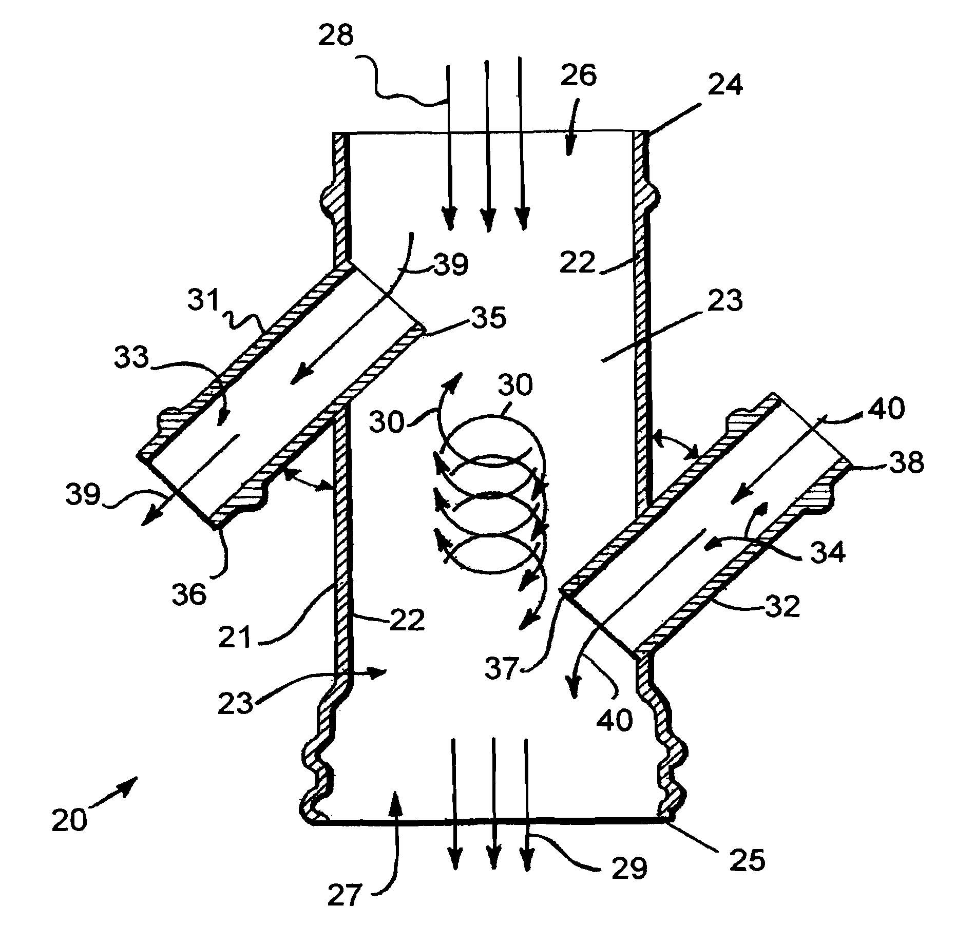
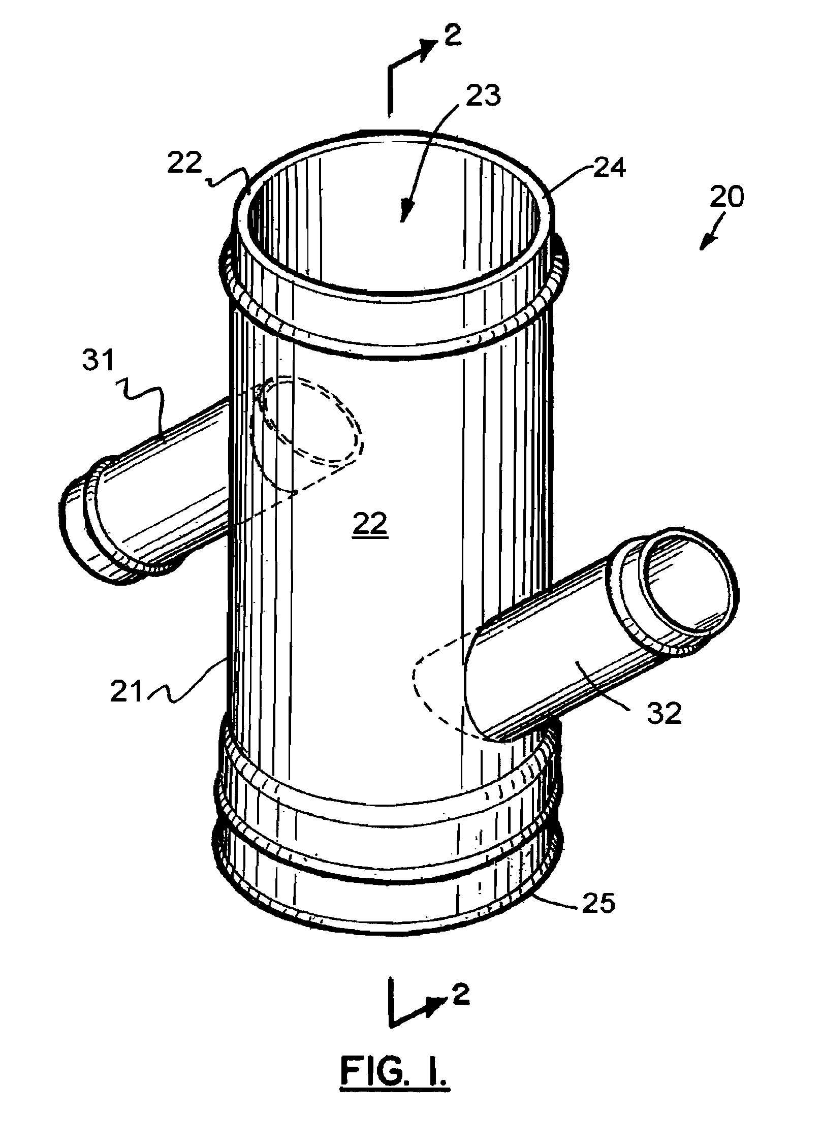
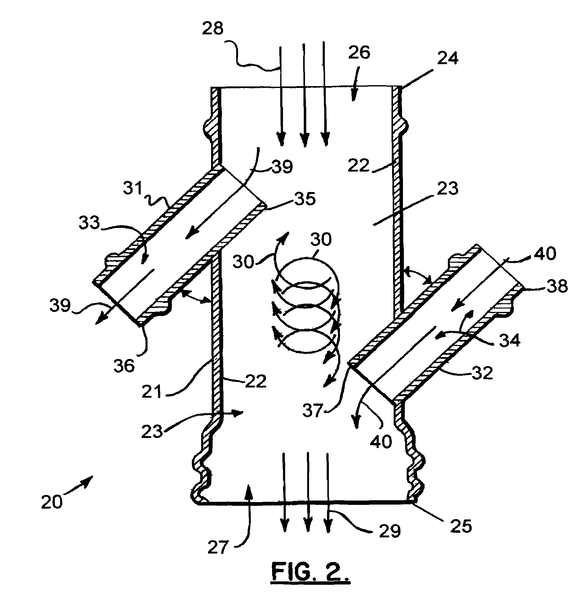
[0022]Preferably, a raised rigid semi-circle shaped lip extends from the backside of the cold water diversion opening into the mixing manifold creating a partial blockage or impediment of the source water flow stream causing a portion of the cold water flow stream to divert into the cold water diversion opening and through the piping to the heating unit. This protruding lip partially blocks and obstructs the water flow inducing suction and flow into the pipe to the heating unit. This partial blockage in the mixing manifold also creates turbulence in the source water flow at and beyond the cold water diversion opening that aids in mixing at the superheated water inflow point. The lip can be a rigid metal concave half circle having for example a ⅛ inch (0.32 cm) width and 1.5 inch to 2 inch (3.81 cm to 5.08 cm) height at its highest point with tapering to meet flush with the side of the mixing manifold at the ends of the semi-circle of the lip; however, the lip can be many shapes, sizes and locations in the mixing manifold to induce suction and create turbulence in the mixing manifold.
[0023]The hot water return opening in the manifold for attachment of piping for the superheated water is preferably located downstream of the cold water diversion opening in the flowing source water in the mixing manifold of the outflow pipe. The hot water return opening for delivery of superheated water preferably likewise has a lip extending into the stream of flowing water creating further turbulence in the water resulting in greater mixing action of the superheated water with the continuously flowing cold water creating arise in temperature of the cold water as it passes along the mixing manifold and through the piping to the frac tanks serving as surge tanks (or directly to mixing tanks if there are no frac tanks acting as surge tanks). This second lip located on the front side or upstream side of the opening provides a partial blocking of the flow of cold water aiding in the flow of the superheated water into the mixing manifold. This lip adjacent to the opening on the hot water return opening is optimally of the same size and shape of the cold water diversion lip; however, this lip can also be utilized in many shapes, sizes and locations in the mixing manifold to partially block flow to facilitate hot water flow into the mixing manifold and create additional turbulence in the mixing manifold.
[0024]Additional mixing of the hot and cold water occurs beyond the mixing manifold as the water flow is piped into and fills the optional frac tanks if used and then piped as operations dictate to mixing tanks to frac pumping units and to downhole. The heated water is delivered and can be temporarily held in frac tanks or surge tanks or pumped directly to mixing tanks without surge tanks. The apparatus and process substantially reduce the number of required frac tanks (or even eliminate the need for frac tanks). In one embodiment of the described process, approximately six to eight 500 bbl (59.6 kl) frac tanks are utilized, which are used as a safety buffer between the water flow and the pumping operations, in the case of a mechanical breakdown or operational problems.
[0033]Through testing in cold temperatures, the inventor has learned that heating water from around freezing to about 40 degrees F. (4.4° C.) takes a great degree of heat. One might need more heaters when heating water from near freezing, or one might initially preheat some water in frac tanks (e.g., 3 or 4 up to 50 or 100 frac tanks) to add heat one needs to move the temperature of the water up from near freezing to about 40 degrees F. (4.4° C.). One could also add heating in a water pit itself to help raise the water temperature to around 40 degrees F. (4.4° C.). Also, when a water source contains ice, it is best to withdraw only liquid water, and no ice, from the water source. Otherwise, a good amount of heat can be lost melting the ice.

Problems solved by technology

In connection with production of oil or gas from a geological formation, the production may have a poor flow rate due to low permeability or from damage or clogging of the formation during drilling particularly in formations of tight sands with low porosity and oil & gas shales.
When the pumped fluid mixture reaches sufficient pressures, the formation will fracture, creating the permeability required to release the captured hydrocarbons.
(even as low as below freezing) which is generally an unsuitably cold temperature for the fracing process.
However, due to the time lapse between heating (which is typically done the night before the fracing operations) significant thermal loss occurs.
The extensive over-heating is a substantial expense and energy waste.
The number of frac tanks can typically range from 20-700 tanks (the average at the Marcellus Shale (located in western New York extending south to Tennessee) is 500 tanks)—currently it costs around $500-2,000 per frac tank in a typical fracing process (delivery, rental, cleaning, and demobilization of the tank), so these frac tanks are a substantial expense in the fracing process.
Typically a substantial amount of safety issues in fracing operations involves the handling of frac tanks.

Method used


Image

  • Water heating apparatus for continuous heated water flow and method for use in hydraulic fracturing
  • Water heating apparatus for continuous heated water flow and method for use in hydraulic fracturing
  • Water heating apparatus for continuous heated water flow and method for use in hydraulic fracturing

Examples


Embodiment Construction

[0049]FIGS. 1-4 and 6-12 show preferred embodiments of the apparatus of the present invention, designated generally by the numeral 10 in FIGS. 3 and 6. Alternate embodiments are designated by the numeral 110 in FIG. 4, by the numeral 210 in FIG. 7, by the numeral 310 in FIG. 8, by the numeral 410 in FIG. 9, by the numeral 510 in FIG. 10, by the numeral 610 in FIG. 11, and by the numeral 710 in FIG. 12. In FIG. 6, a water source 11 can be a reservoir, lake or other source of water.

[0050]Mobile heater apparatus 12 is used to super heat water for use in frac operations in an oil well. In general, such frac operations can be seen in U.S. Pat. No. 4,137,182, hereby incorporated herein by reference.

[0051]Mobile heater 12 is a transportable heating apparatus and includes a truck 13 and a trailer 14. Trailer 14 carries a heating vessel 15 which can be, for example, a tank or piping that holds water and that can be heated with electrical or other heating elements or with propane or preferabl...


PUM


Abstract

A method of hydraulic fracturing of an oil producing formation includes the provision of a heating apparatus which is transportable and that has a vessel for containing water. A water stream of cool or cold water is transmitted from a source to a mixer, the cool or cold water stream being at ambient temperature. The mixer has an inlet that receives cool or cold water from the source and an outlet that enables a discharge of a mix of cool or cold water and the hot water. After mixing in the mixer, the water assumes a temperature that is suitable for mixing with chemicals that are used in the fracturing process, such as a temperature of about 40° -120° F.+(4.4 - 48.9° C.+). An outlet discharges a mix of the cool and hot water to surge tanks or to mixing tanks. In the mixing tanks, a proppant and an optional selected chemical or chemicals are added to the water which has been warmed. From the mixing tanks, the water with proppant and optional chemicals is injected into the well for part of the hydraulic fracturing operation.

Description

CROSS-REFERENCE TO RELATED APPLICATIONS[0001]Incorporated herein by reference are my prior U.S. provisional patent application No. 61 / 297,097, filed 21 Jan. 2010, my prior U.S. provisional patent application no. 61 / 254,122, filed 22 Oct. 2009, and my prior U.S. provisional patent application No. 61 / 276,950, filed 18 Sep. 2009. Priority of these applications is hereby claimed.STATEMENT REGARDING FEDERALLY SPONSORED RESEARCH OR DEVELOPMENT[0002]Not applicableREFERENCE TO A “MICROFICHE APPENDIX”[0003]Not applicableBACKGROUND OF THE INVENTION[0004]1. Field of the Invention[0005]The present invention relates to a method and apparatus for the continuous preparation of heated water flow for use in hydraulic fracturing.[0006]2. General Background of the Invention In connection with production of oil or gas from a geological formation, the production may have a poor flow rate due to low permeability or from damage or clogging of the formation during drilling particularly in formations of tig...

Claims


Application Information

Patent Timeline
Patent Type & Authority Patents(United States)
IPC IPC(8): E21B43/24
CPCE21B43/26G05D23/1306F24H1/125E21B43/267E21B43/2607
Inventor HEFLEY, RANSOM MARK
Owner HEAT ON THE FLY
Why Eureka
Try Eureka