Implantable multi-wavelength venous oxygen saturation and hematocrit sensor and method

a multi-wavelength, hematocrit technology, applied in the field of implantable self-calibration optical sensors, can solve the problems of high noise in single-wavelength oxymetry systems, can only be used to measure relative changes in oxygen saturation, and the relationship between scattering and oxygen saturation is different for each different wavelength, so as to improve the accuracy of oxygen saturation calculation

Active Publication Date: 2012-05-08
PACESETTER INC
View PDF17 Cites 51 Cited by
  • Summary
  • Abstract
  • Description
  • Claims
  • Application Information

AI Technical Summary

Benefits of technology

[0008]In accordance with a specific embodiment of the present invention, an implantable oxymetry system includes an oxymetry sensor which comprises an implantable housing including a window through which light can pass. Included within the housing are a plurality of light sources, a measurement light sensor and a calibration light sensor. Each light source transmits light of a single wavelength. A portion of the light of each wavelength exits the housing through the window. An opaque barrier between the light sources and the measurement light sensor blocks most light from traveling directly from the light source to the measurement light sensor without passing through the blood. The measurement light sensor detects light of each wavelength scattered back into the housing through the window, and produces a measurement signal that is indicative of the intensity of the light of each wavelength detected by the measurement light sensor. A processor calculates ratios of the measurement signals for the plurality of wavelengths of light to determine oxygen saturation and hematocrit. Oxygen saturation is calculated using equations which are corrected based on hematocrit to improve the accuracy of the oxy

Problems solved by technology

However, single wavelength oxymetry systems are highly susceptible to noise and can only be used to measure relative changes in oxygen saturation.
However, on

Method used


Image

  • Implantable multi-wavelength venous oxygen saturation and hematocrit sensor and method
  • Implantable multi-wavelength venous oxygen saturation and hematocrit sensor and method
  • Implantable multi-wavelength venous oxygen saturation and hematocrit sensor and method

Examples


Embodiment Construction

[0024]The following description is of the best modes presently contemplated for practicing various embodiments of the present invention. This description is not to be taken in a limiting sense but is made merely for the purpose of describing the general principles of the invention. The scope of the invention should be ascertained with reference to the claims. In the description of the invention that follows, like numerals or reference designators will be used to refer to like parts or elements throughout. Also, the left-most digit of a reference number identifies the drawing in which the reference number first appears.

Oxymetry Sensors

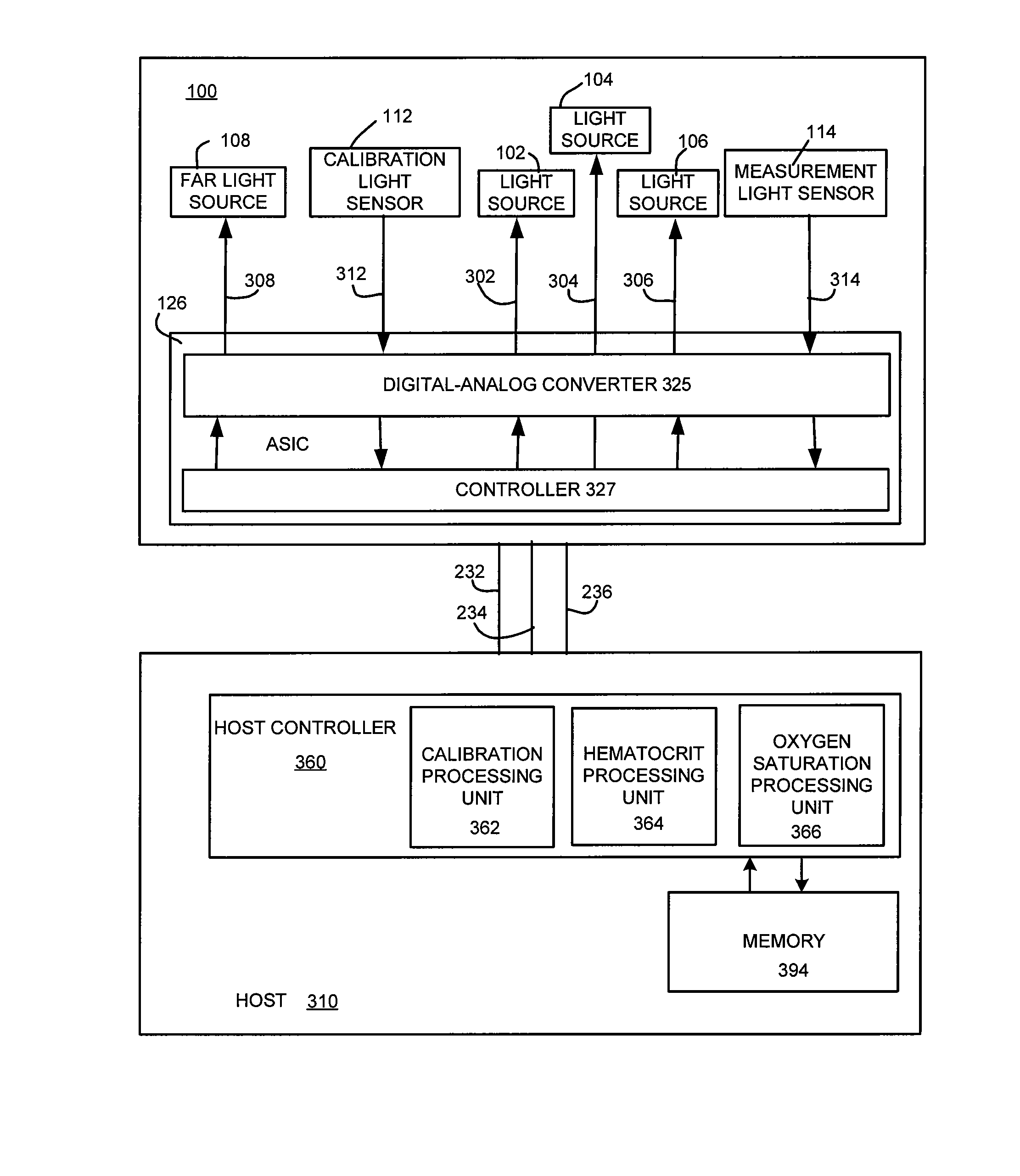
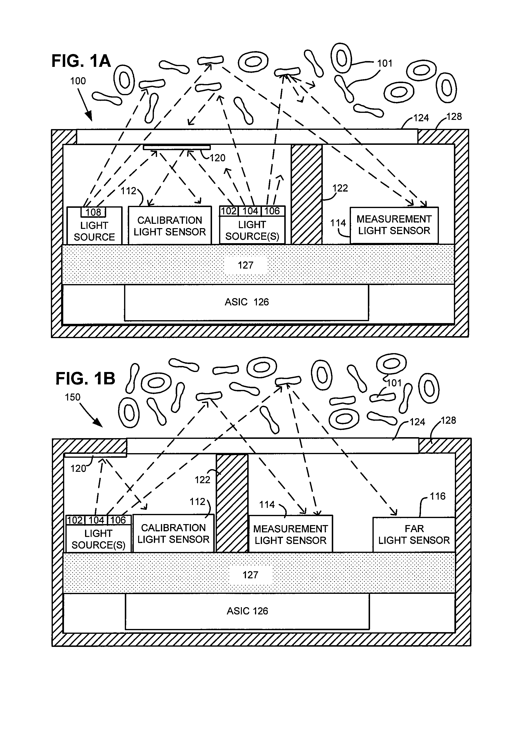
[0025]Referring now to FIG. 1A, there is shown an exemplary oxymetry sensor 100 suitable for use in an embodiment of the present invention. Oxymetry sensor 100 uses light sources of three different-centered wavelengths to obtain measures of blood-oxygen saturation. Oxymetry sensor 100 emits light into the blood. The absorption and / or scattering of the l...


PUM


Abstract

An intravenous implantable optical sensor assesses the relative absorbance of multiple wavelengths of light in order to determine oxygen saturation. The calculation of oxygen saturation is enhanced by use of a function of hematocrit which is derived from the relative absorbance of light of an isobestic wavelength along two different length paths through the blood. The use of the hematocrit-dependent term and multiple wavelengths of light to calculate oxygen saturation provides results that are less susceptible to noise and variation in hematocrit and thus provides a more accurate measure of oxygen saturation over a wider range of conditions than previously possible. The optical sensor may form part of an implantable system which performs the calculation of oxygen saturation and uses the results for a diagnostic or therapeutic purpose.

Description

FIELD OF THE INVENTION[0001]Embodiments of the present invention relate to implantable self-calibrating optical sensors that are used, e.g., for obtaining measures of blood oxygen saturation and / or hematocrit.BACKGROUND[0002]Blood oxygen saturation is the relative amount of oxygenated hemoglobin in all of the hemoglobin present in the blood stream. This hemoglobin is packaged in biconcave discs of approximately 10 micrometers diameter which commonly occur with a density of approximately five million red blood cells per cubic millimeter. When radiant energy (e.g., light) is incident upon red blood cells, the red blood cells both reflect and absorb the incident radiant energy. Oxygenated and non-oxygenated hemoglobin reflect and absorb the radiant energy incident on the red blood cells differently. Thus, oxygen saturation may be determined by analyzing the radiant energy scattered back from the red blood cells.[0003]An oxymetry sensor can use radiant energy of one, two or more differe...

Claims


Application Information

Patent Timeline
IPC IPC(8): A61B5/1455
CPCA61B5/14552A61B5/1459A61N1/36557
Inventor NABUTOVSKY, YELENABORNZIN, GENE A.FARAZI, TARANEH GHAFFARIPOORE, JOHN W.
Owner PACESETTER INC
Why Eureka
Try Eureka