Reforming apparatus for fuel cell

a fuel cell and apparatus technology, applied in the direction of electrochemical generators, sustainable manufacturing/processing, chemical/physical/physicochemical processes, etc., can solve the problems of deteriorating the reforming performance of the reformer, increasing the diameter of the reformer, and complicated passages, etc., to achieve the effect of simplifying the structur

Inactive Publication Date: 2012-05-15
NIPPON OIL CORP
View PDF19 Cites 5 Cited by
  • Summary
  • Abstract
  • Description
  • Claims
  • Application Information

AI Technical Summary

Benefits of technology

[0014]The present invention has been made under such circumstances, and an advantage of embodiments of the present invention is to provide a reforming apparatus, for use in a fuel cell, having a simplified structure.
[0015]Another advantage thereof is to provide a technology by which to improve the thermal efficiency in a fuel cell reforming apparatus.
[0016]Still another advantage thereof is to provide a technology for improving the reforming efficiency in a fuel cell reforming apparatus.

Problems solved by technology

When the utility gas, propane gas or the like containing the organosulfur component is directly supplied to the reformer, the organosulfur component is adhered to catalyst in the reformer, thus deteriorating the reforming performance of the reformer.
As a result, the passage gets complicated.
Therefore, the diameter of the reformer becomes larger and at the same time the reforming apparatus as a whole becomes complicated, thus contributing to an increased size thereof.
However, in the aforementioned reformer, the passage for the reformed gas is still complicated and, at the same time, different catalysts need to be placed in a plurality of passages.
Hence, the process of operation is cumbersome and complicated, thus causing a cost increase in manufacturing the apparatus.
Also, if a desulfurizing function is to be added to such a reformer as the above, the structure thereof will be further complicated.

Method used


Image

  • Reforming apparatus for fuel cell
  • Reforming apparatus for fuel cell
  • Reforming apparatus for fuel cell

Examples


first embodiment

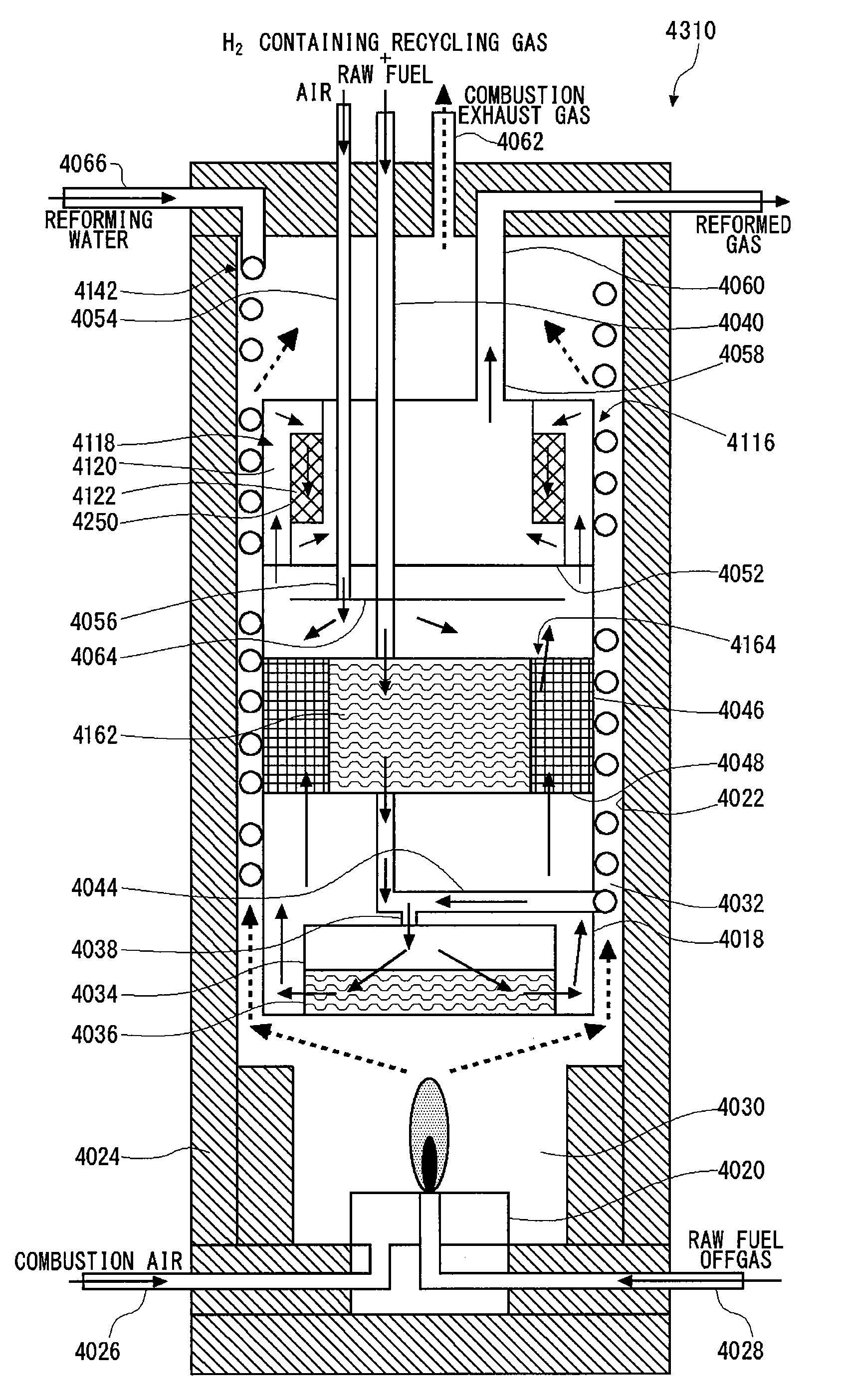
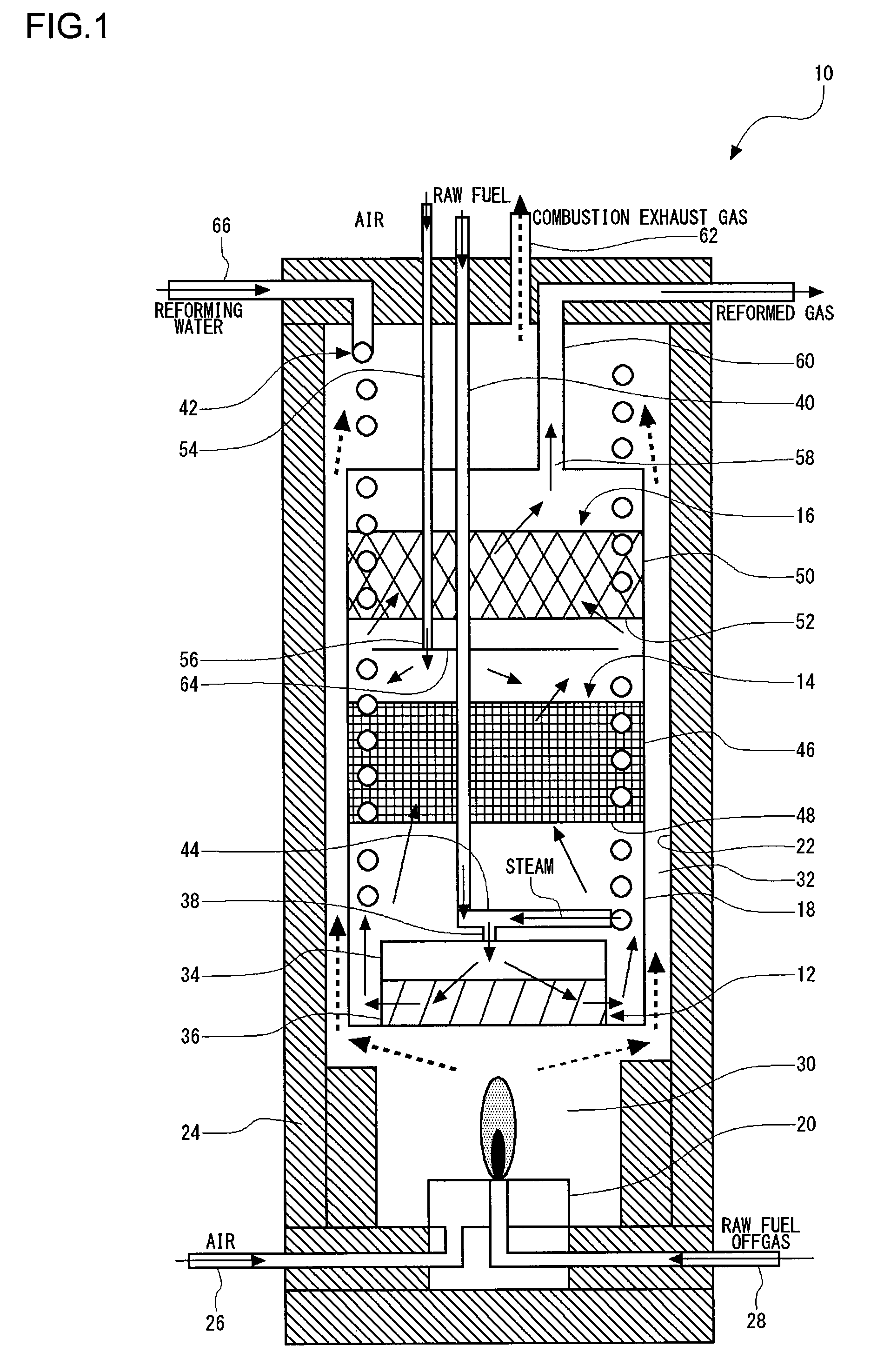
[0054]FIG. 1 is a cross-sectional view illustrating a structure of a reforming apparatus 10 for use in a fuel cell according to a first embodiment of the present invention. The fuel cell reforming apparatus 10 produces hydrogen-rich reformed gas by subjecting methane, propane, butane or the like, which is a raw fuel, to steam reforming.

[0055]The fuel cell reforming apparatus 10 includes a reformer 12 for producing the reformed gas from the raw fuel and steam, a shift reactor 14 for reducing the carbon monoxide contained in the reformed gas through water-gas shift reaction, a selective oxidation unit 16 for reducing the carbon monoxide contained in the reformed gas which has passed through the shift reactor 14 by performing selective oxidation on said carbon monoxide through a selective oxidation reaction, a reforming reaction tube 18 for housing linearly the reformer 12, the shift reactor 14 and the selective oxidation unit 16 in this order, a burner 20, as a combustion means, for g...

second embodiment

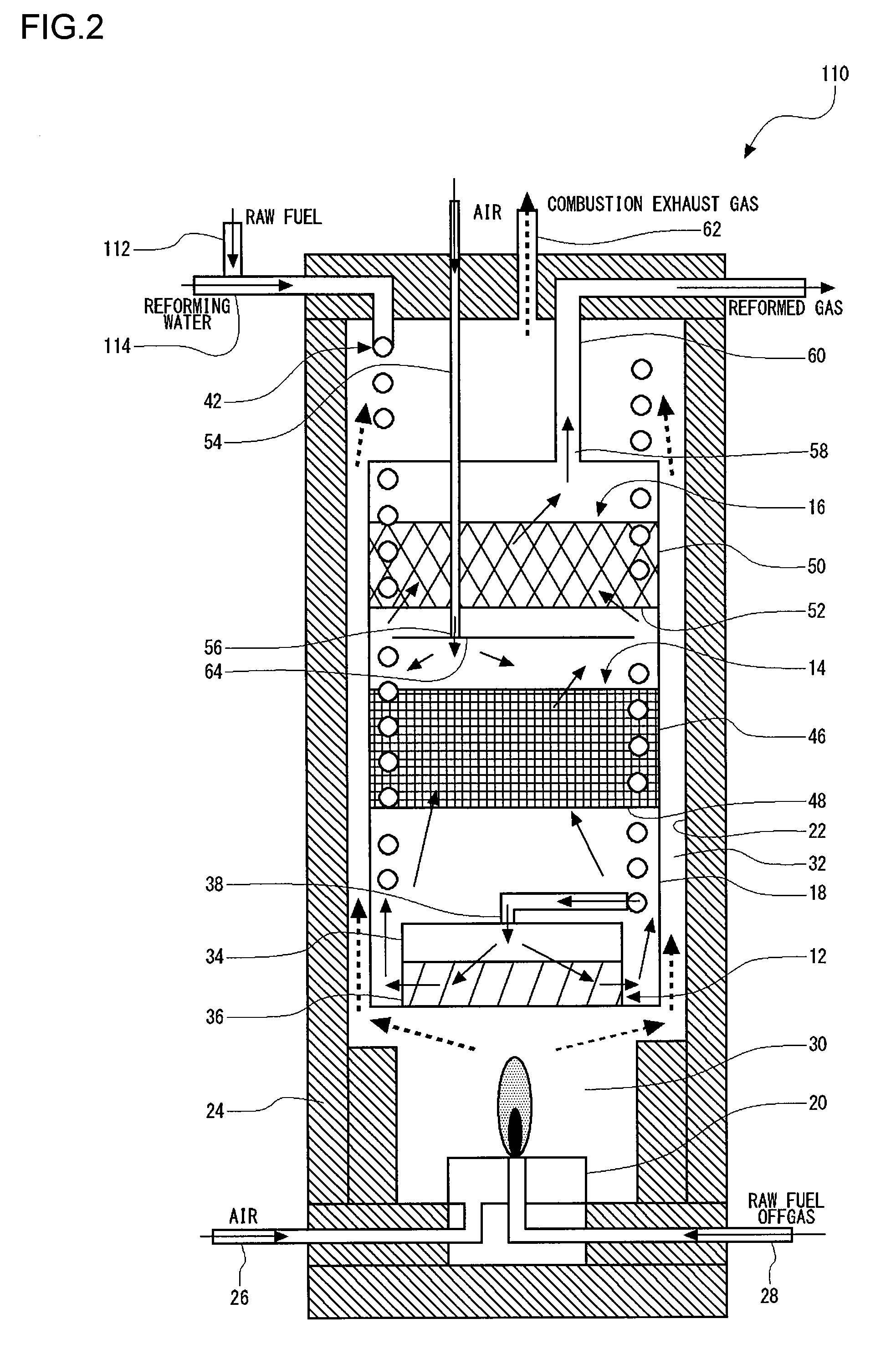
[0076]FIG. 2 is a cross-sectional view illustrating a structure of a reforming apparatus 110 for use in a fuel cell according to a second embodiment of the present invention. The fuel cell reforming apparatus 110 according to the second embodiment includes a steam supply passage 42 in which the water is evaporated by the heating of combustion exhaust gas to supply the steam to a reformer 12, and a raw fuel supply passage 112 for supplying the raw fuel to the reformer 12. The raw fuel supply passage 112 joins together with the steam supply passage 42 at a merging part 114 disposed upstream of a position where the water passing through the steam supply passage 42 is evaporated. With this structure, the temperature of the raw fuel is raised as a result of the heating by the combustion exhaust gas, and simultaneously the water is evaporated in the steam supply passage 42. Hence, the length of the raw fuel supply passage 112 can be made shorter.

[0077]The raw fuel passage 112 joins togeth...

third embodiment

[0078]In the fuel cell reforming apparatus according to each of the above-described embodiments, the steam supply passage 42 is so provided that it passes through inside the reforming reaction tube 18 and it penetrates the catalyst layer 46 in the shift reactor 14 and the catalyst layer 50 in the selective oxidation unit 16. Accordingly, the catalyst temperature drops more than necessary in an area of the steam supply passage 42 directly contacted by the catalyst layer 50. Thus, there is a possibility that the reaction does not progress sufficiently. In the light of this, the arrangement of the steam supply passage is devised in this third embodiment, thus preventing the temperature of the catalyst layer from dropping more than necessary.

[0079]FIG. 3 is a cross-sectional view illustrating a structure of a reforming apparatus 210 for use in a fuel cell according to a third embodiment of the present invention. The fuel cell reforming apparatus 210 according to the third embodiment dif...


PUM


Abstract

In a reforming apparatus, for use in a fuel cell, for reforming a raw fuel into a hydrogen-rich reformed gas, a reformer generates the reformed gas from the raw fuel. A shift reactor reduces carbon monoxide contained in the reformed gas through a shift reaction. A selective oxidation unit reduces the carbon monoxide contained in the reformed gas that has passed through the shift reactor by performing selective oxidation on the carbon monoxide. A reforming reaction tube houses linearly the reformer, the shift reactor and the selective oxidation unit in this order. A combustion means produces combustion exhaust gas by combusting the raw fuel. An outer casing is placed around the reforming reaction tube, and the outer casing has a larger diameter than that of the reforming reaction tube. A heated flow passage through which the combustion exhaust gas passes to heat the reforming reaction tube is formed between the reforming reaction tube and the outer casing.

Description

CROSS-REFERENCE TO RELATED APPLICATIONS[0001]This application is based upon and claims the benefit of priority from the prior Japanese Patent Application No. 2007-252653, filed on Sep. 27, 2007, Japanese Patent Application No. 2007-252654, filed on Sep. 27, 2007, Japanese Patent Application No. 2007-252655, filed on Sep. 27, 2007, Japanese Patent Application No. 2007-252656, filed on Sep. 27, 2007, Japanese Patent Application No. 2007-252657, filed on Sep. 27, 2007, Japanese Patent Application No. 2007-252658, filed on Sep. 27, 2007, Japanese Patent Application No. 2008-070054, filed on Mar. 18, 2008 and Japanese Patent Application No. 2008-070055, filed on Mar. 18, 2008, the entire contents of which are incorporated herein by reference.BACKGROUND OF THE INVENTION[0002]1. Field of the Invention[0003]The present invention relates to a reforming apparatus, for use in a fuel cell, which reforms raw fuel into a reformed gas used in a fuel cell system.[0004]2. Description of the Related ...

Claims


Application Information

Patent Timeline
Patent Type & Authority Patents(United States)
IPC IPC(8): B01J8/04B01J10/00
CPCC01B3/384H01M8/0631H01M8/0675C01B2203/0233C01B2203/0283C01B2203/044C01B2203/047C01B2203/0495C01B2203/066C01B2203/0811C01B2203/0822C01B2203/0827C01B2203/0894C01B2203/1241C01B2203/1247C01B2203/127C01B2203/148Y02E60/50Y02P20/10
Inventor FUJU, AKIRAKADOWAKI, MASATAKAKOBAYASHI, KAZUMINAKAJIMA, KAZUAKISATO, YASUSHISAMURA, KEN
Owner NIPPON OIL CORP
Why Eureka
Try Eureka