High filling flow water phantom

a water phantom and high filling flow technology, applied in the field of water phantoms, can solve the problems of cumbersome and time-consuming handling of these large scanning water phantoms, aggravate the drawback, and require additional time for conventional water phantoms, and achieve the effect of fast setup and fast measuremen

Active Publication Date: 2012-05-22
ION BEAM APPL
View PDF5 Cites 13 Cited by
  • Summary
  • Abstract
  • Description
  • Claims
  • Application Information

AI Technical Summary

Benefits of technology

[0012]The water phantom comprises: a water tank having a lower base and side walls; and a water supply unit which supplies water to the water tank. The water tank comprises an intermediate or upper base that forms, together with side walls and the lower base, a closed lower tank underneath the intermediate base and an upper tank above the intermediate or upper base. The closed lower tank is connected to the supply unit and allowing the flow of water toward said upper tank through a plurality of water admission passages defined in the intermediate base. These water admission passages are effective and are configured to provide an unturbulent water flow within said water tank at least during the filling of the upper tank.
[0017]In another aspect, a method of measuring and determining the dose distribution of a radiation produced by a particle beam or photon radiation beam using the above described water phantom is described herein. In an important aspect the method includes a method for making commissioning tests of a radiation therapy apparatus. The new commissioning method provides drastically reduced commissioning times compared to commissioning times for known water phantoms.

Problems solved by technology

Though the use of water phantoms has been an established standard since many years, the handling of these large scanning water phantoms is cumbersome and time consuming partly because of the long filling and emptying time of the water tank.
The presence of such water waves is actually a problem for the setup of the water phantom since they make the water surface very turbulent for quite a while even after filling the tank.
Consequently, conventional water phantoms require additional time before one can start measurements waiting for the water within the tank to calm down.
This drawback is even aggravated when performing measurements in TPR configuration wherein the water level is changed during the measurement.
In fact, conventional water phantoms require that the flow rate of the incoming water into the water tank is kept low since a high flow rate would create waves within the tank and make the water very turbulent thereby leading to noisy and inaccurate TPR measurements.

Method used


Image

  • High filling flow water phantom
  • High filling flow water phantom
  • High filling flow water phantom

Examples


second embodiment

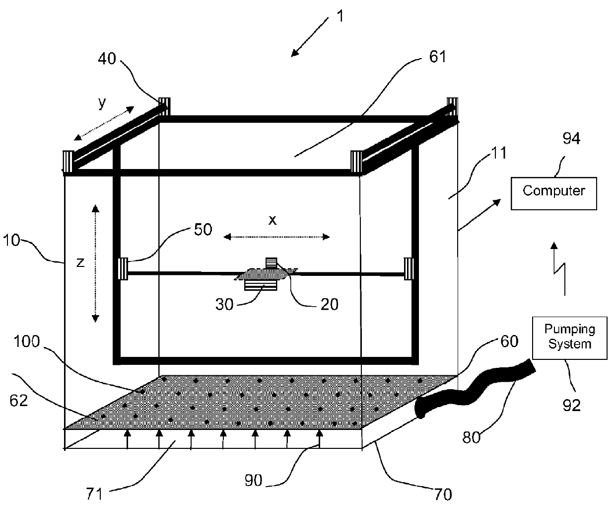
[0030]FIG. 2 is a perspective view of a water phantom according to a According to this embodiment the upper base 60 further comprises a detector comprised of a matrix of sensors 100 which are arranged on the surface of the upper base 60 in between the openings 62 in the upper base. In a basic configuration the matrix of sensors is made up of 169 diodes (13×13) evenly distributed over the upper base 60 (spacing between diodes approximately 3.5 cm). In a high-level configuration, the matrix may comprise a higher number of diodes along the central X-, Y-axes, and diagonals of the upper base 60 with a spacing of approximately 0.5 cm in order to measure central axis profiles with a high resolution. According to a variant of this embodiment, the matrix is made up of 1600 ionization chambers and has an active area of 40 cm×40 cm. Each ionization chamber has a diameter of 3.8 mm and a height of 2 mm and is spaced from the others with a pitch of 6.5 mm. This embodiment is particularly advan...

third embodiment

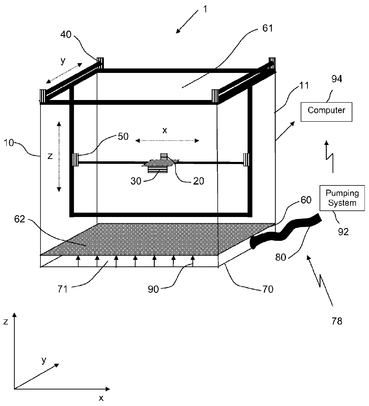
[0032]FIG. 4 is a perspective view of a water phantom according to a According to this embodiment, the lower base 70 has an irregular thickness so that the closed lower tank 71 presents a slanted shaped bottom surface having one of the four corners slightly deeper than the others. Since the connection line 80 connecting the pumping system to the closed lower tank 71 is opportunely located near this deeper corner, the presence of this slanted shaped bottom surface ensures that all water can be easily and quickly evacuated from the water tank 10 without having residual water within the water tank which could activate algae growth. It should be noticed that conventional water phantoms typically avoid this problem by manually raising one side of the water tank off the ground or by using expensive water filtration systems. It is evident that the water phantom according to this embodiment is less complex and less expensive with respect to conventional water phantoms.

[0033]FIG. 5 is a per...

fourth embodiment

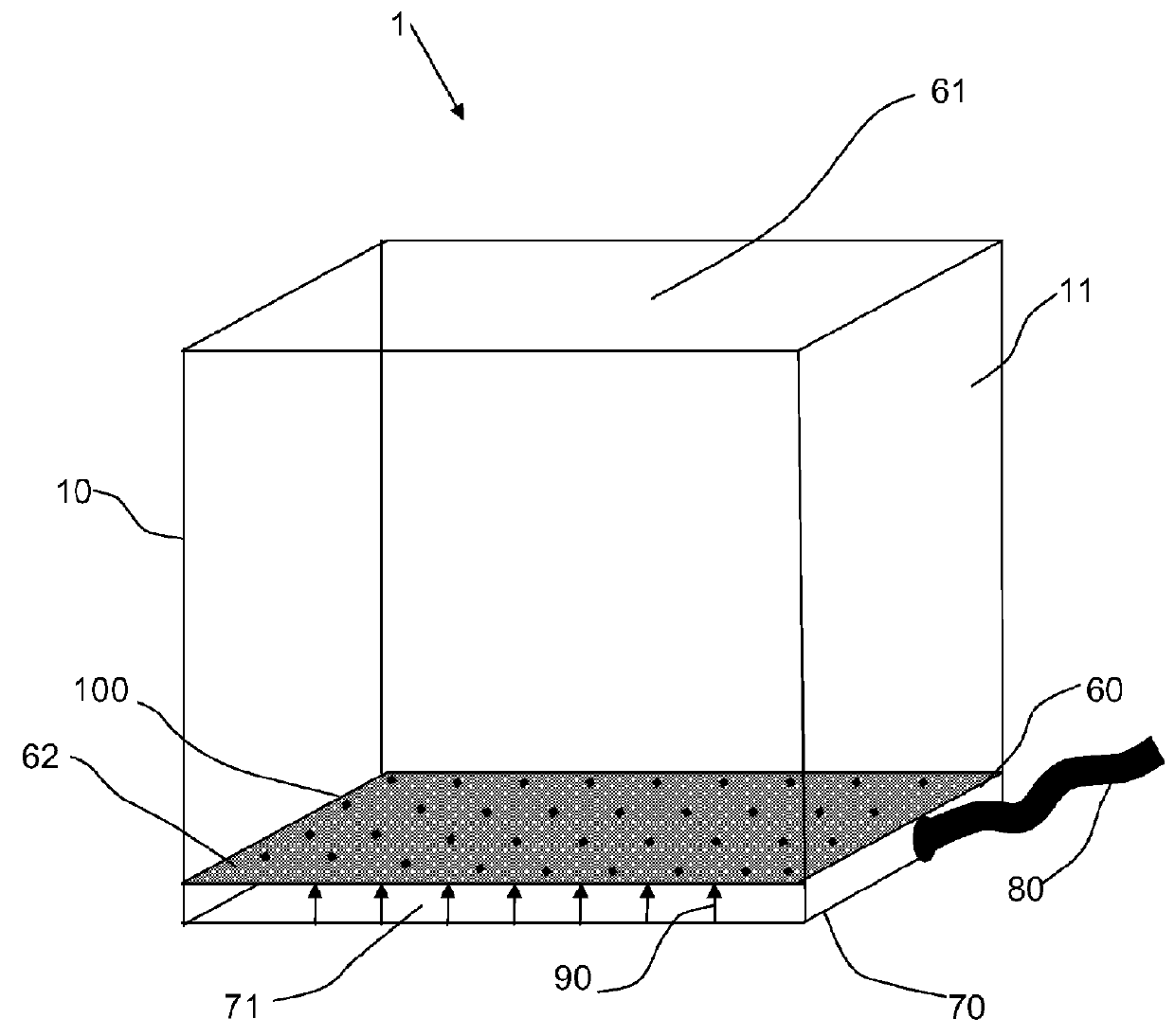
[0034]FIG. 6 is a perspective view of a water phantom according to a variant of the The water phantom according to this variant is similar to the one represented in FIG. 3 wherein the acquisition detector 20 as well as the driving units 30, 40, 50 are removed and wherein measurements of TPR curves are provided by the plurality of detectors 100 arranged in between the openings 62 of the upper base 60. In this variant the closed lower tank 71 further has a slanted shaped bottom surface having one of the four corners slightly less deep with respect to the others.

[0035]The water phantom described herein presents following advantages:

[0036]One of the most significant drawbacks of the prior art is the enormous time amount usually required for the commissioning tests, especially when performing measurements in TPR configuration. By using the water phantom, the water phantom described herein can drastically reduce time by providing a water phantom which is configured to be filled with high...


PUM


Abstract

The present invention is related to a water phantom for measuring and determining the dose distribution of radiation produced by a particle beam or photon radiation beam comprising: a water tank, the water tank having a lower base and side walls; supply means for supplying water to the water tank. The water tank comprises an intermediate base that forms, together with side walls and said lower base, a closed lower tank underneath said intermediate base and an upper tank above said intermediate base, the closed lower tank being connected to the supply means and allowing the flow of water toward said upper tank through a plurality of water admission passages defined in the intermediate base to provide an unturbulent water flow within said water tank 2.

Description

FIELD[0001]The present invention relates to a water phantom for measuring and verifying the dose distribution of a photon radiation beam or particle beam generated by a radiation therapy apparatus.BACKGROUND AND STATE OF THE ART[0002]Water phantoms are well known in the art and are typically used for establishing the effect of ionizing radiations over the human body. Such a water phantom mainly comprises a water tank (with a volume of about 250 liters), and is equipped with driving unit which moves a radiation detector (e.g. a water-tight air ion chamber probe, a diode or an array of sensors) within the water tank volume into a plurality of measuring positions. The water tank is filled and emptied by means of a pump control mechanism from an external water reservoir.[0003]A well known water phantom is, for example, the “Blue Phantom” manufactured by the assignee of this application, Ion Beam Applications S.A. Louvain-La-Neuve, Belgium. In such a water phantom, the detector may be a ...

Claims


Application Information

Patent Timeline
Patent Type & Authority Patents(United States)
IPC IPC(8): G01D18/00G01T1/16
CPCG01T1/169A61N5/1075A61N2005/1076A61N2005/1087
Inventor CELI DE LA TORRE, JUAN-CARLOSREINHOLD, STEFANHARMANSA, ROMANPLOMPEN, ROB
Owner ION BEAM APPL
Why Eureka
Try Eureka