Vehicle load floor support with integral air duct

a floor support and vehicle load technology, applied in the direction of electric propulsion mounting, battery/fuel cell control arrangement, electric propulsion, etc., can solve the problem that the fan generates a level of noise that requires attenuation for passenger comfort, and achieve the effect of eliminating the complexity of connecting separate tuning structures and optimizing noise attenuation

Inactive Publication Date: 2012-05-29
GM GLOBAL TECH OPERATIONS LLC
View PDF23 Cites 32 Cited by
  • Summary
  • Abstract
  • Description
  • Claims
  • Application Information

AI Technical Summary

Benefits of technology

[0004]The duct may be configured with a main passage that routes from the cooling system to a vent which allows air out of the passenger compartment, so that the cooling system air (e.g., air exhausted from the energy storage system by a fan) is then directed outside of the vehicle. One or more side passages in the duct may be formed in the structural foam load floor support. The side passages can be configured to function as acoustic resonators to optimize noise attenuation. Because other vehicle components may be packaged under the load floor, the structural foam load floor support may be configured with packaging cavities to securely position and retain such components. The shape and routing of the integral duct may be based in part on a necessity to route around these or other vehicle components. Because the duct is integral with the foam load floor support, any “squeak and rattle” noise associated with an interface between a foam load floor support and a separate (non-integrated) duct is avoided. Integrating the side passages with the main passage in the structural foam load floor support eliminates the complexity of connecting separate tuning structure with a separate (non-integrated) duct, while at the same time trying to avoid other components under the load floor.

Problems solved by technology

Some fans generate a level of noise that requires attenuation for passenger comfort.

Method used


Image

  • Vehicle load floor support with integral air duct
  • Vehicle load floor support with integral air duct
  • Vehicle load floor support with integral air duct

Examples


Embodiment Construction

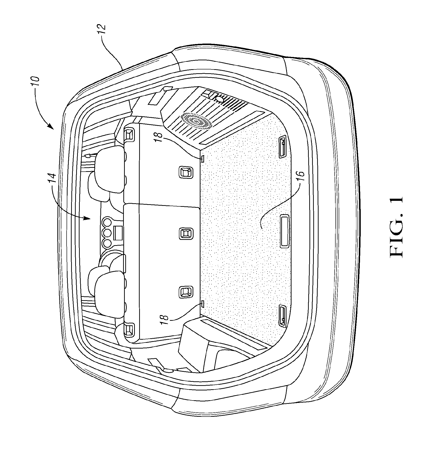
[0011]Referring to the drawings, wherein like reference numbers refer to like components, FIG. 1 shows a hybrid vehicle 10 (such as but not limited to sport utility vehicles (SUVs), minivans, station wagons, and hatchbacks). The hybrid vehicle 10 may be any type of hybrid, i.e., any vehicle with at least two primary sources of power, such as a gasoline electric, diesel electric, or a fuel cell hybrid vehicle. The vehicle 10 has vehicle body structure 12, such as body panels, that define an interior passenger compartment 14 and separate the interior passenger compartment 14 from outside of the vehicle (i.e., from the surrounding environment). A load floor 16 is within the passenger compartment 14 and is movable via hinges 18 from the closed position of FIG. 1 to an open position of FIGS. 2 and 3.

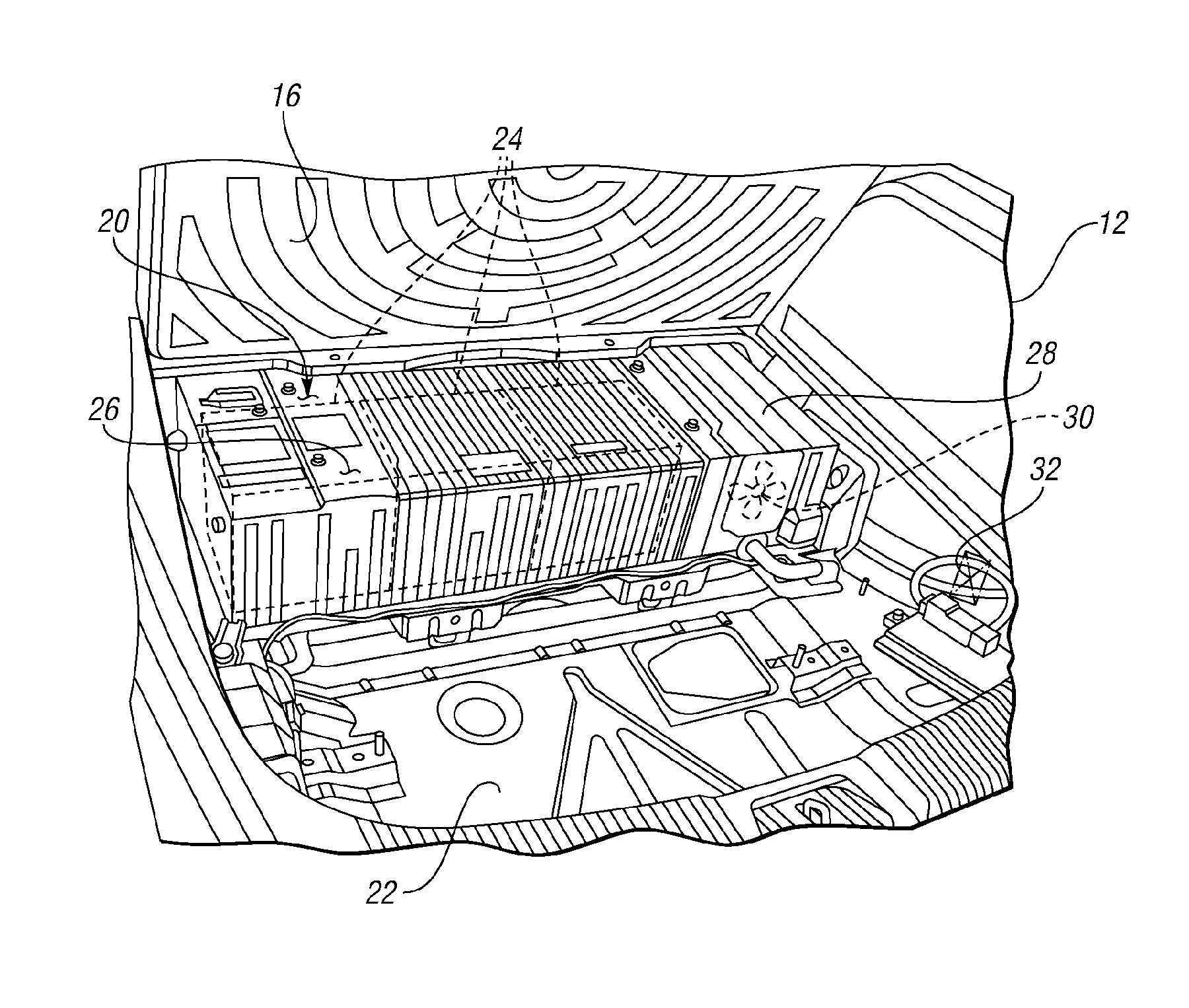
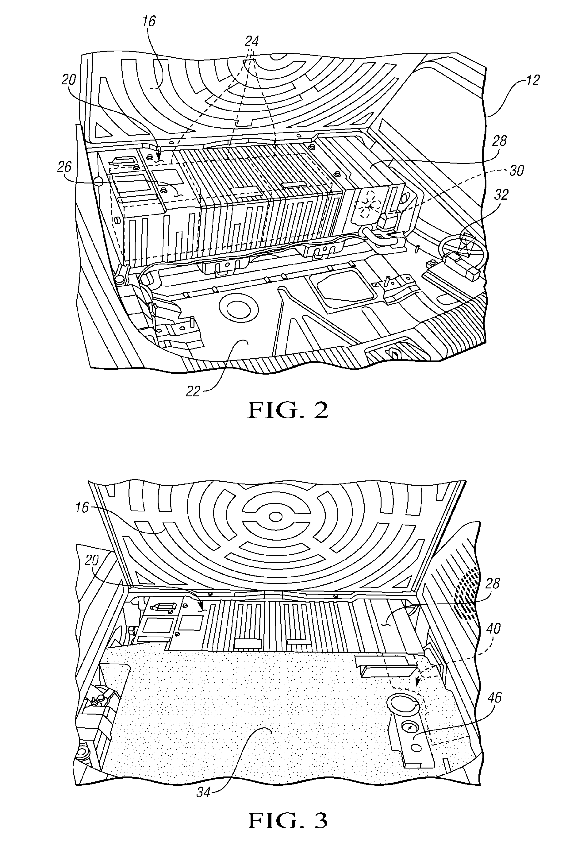
[0012]Referring to FIG. 2, with the load floor 16 open, an energy storage system 20 is visible packaged within the passenger compartment 14, above a floor pan 22 but below the load floor 16. ...


PUM


Abstract

A porous, sound absorbing structural foam load floor support is provided that defines an integral duct. The duct is configured as a ventilation air passage from the air outlet of a heat-emitting component, such as an energy storage system in a hybrid vehicle, so that the load floor support serves both to support the load floor as well as to provide a route for heat dissipation. By integrating the duct within the load floor support, a separate duct, which would have to route around other vehicle components located under the load floor, is not required. The structural foam load floor support is configured to absorb noise of a cooling system for the energy storage system. A porous expanded polypropylene foam is especially well-suited for noise attenuation and load floor support.

Description

TECHNICAL FIELD[0001]The invention relates to a load floor support with an integral air duct, and specifically to a porous, sound absorbing structural foam load floor support with an integral air duct for cooling air for an energy storage system on a vehicle.BACKGROUND OF THE INVENTION[0002]Hybrid vehicles that utilize stored electrical energy in combination with another power source, such as an internal combustion engine or a fuel cell, may offer fuel efficiency and other advantages. Many hybrid vehicles proposed to date (such as but not limited to sport utility vehicles (SUVs), minivans, station wagons, and hatchbacks) have an energy storage system packaged within the vehicle passenger compartment. As the energy storage system emits a significant amount of heat, the heat must be vented outside of the passenger compartment. A fan may be used to assist with directing the heat out of the vehicle. Some fans generate a level of noise that requires attenuation for passenger comfort.SUMM...

Claims


Application Information

Patent Timeline
Patent Type & Authority Patents(United States)
IPC IPC(8): B60K11/06
CPCB60K1/04B60R5/04B60K2001/005B60K2001/0438Y10S903/903Y10S903/952B60L1/003B60L2240/34B60L2270/142B60L50/66B60L58/21B60L58/26Y02T10/70
Inventor PARRETT, ALAN V.STANFORTH, KYLE W.HE, HUAROGGENKAMP, TIMOTHY J.
Owner GM GLOBAL TECH OPERATIONS LLC
Why Eureka
Try Eureka