

Aerodynamic device for detection of wind turbine blade operation
a wind turbine blade and aerodynamic technology, which is applied in the direction of rotors, marine propulsion, vessel construction, etc., can solve the problems of blade icing, reduced lifting capacity, and turbine power outpu
- Summary
- Abstract
- Description
- Claims
- Application Information
AI Technical Summary
Benefits of technology
Problems solved by technology
Method used
Image

Examples
Embodiment Construction
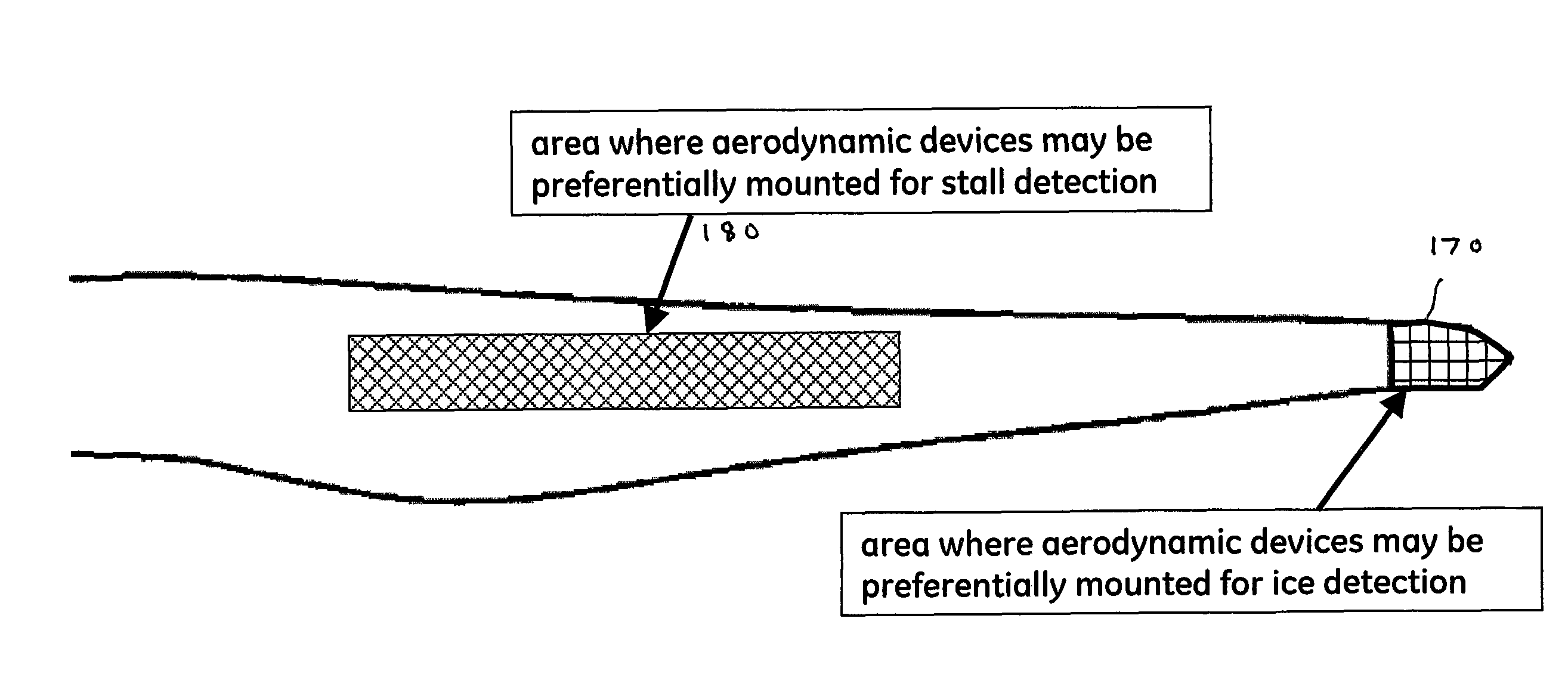
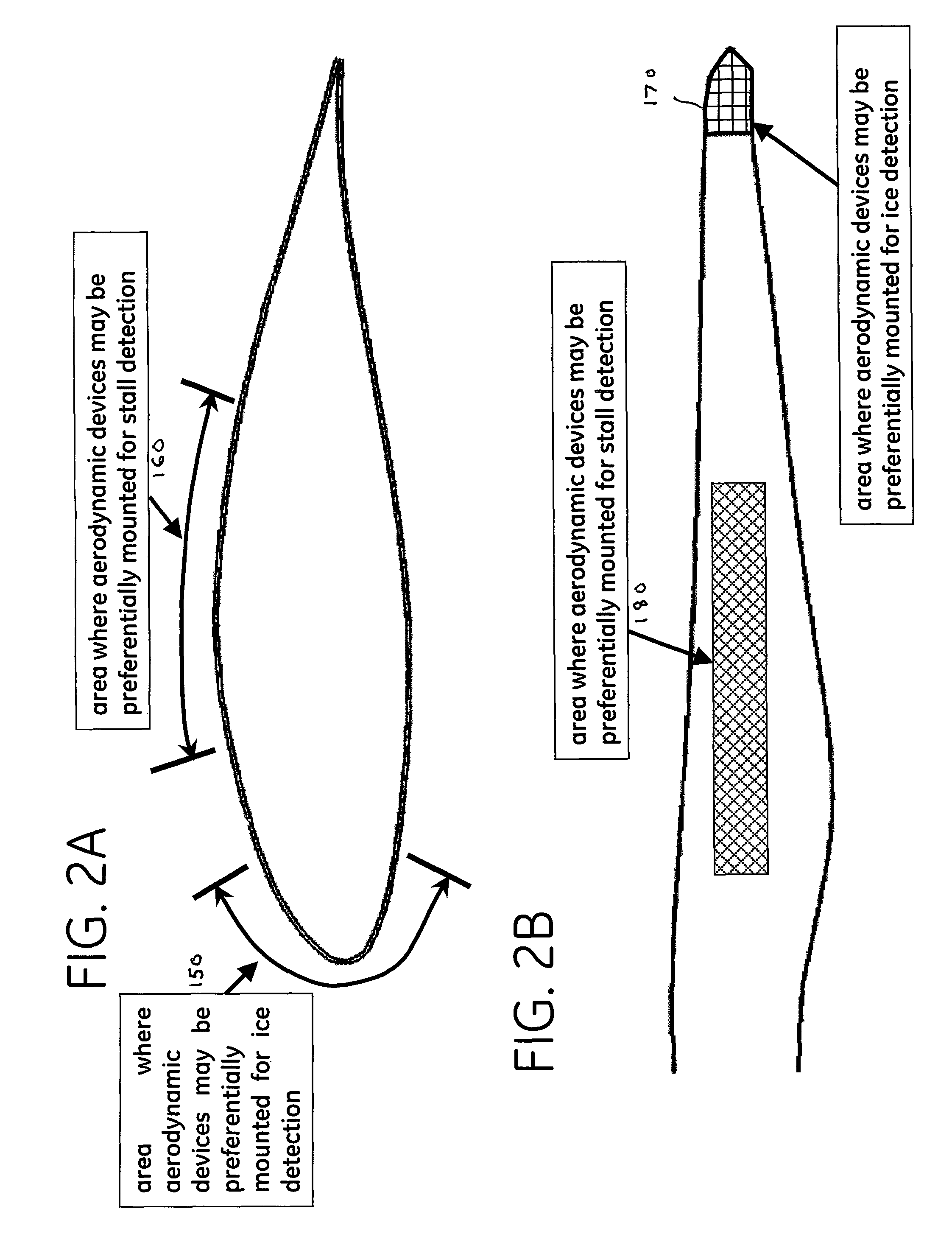
[0021]The following embodiments of the present invention have many advantages, including providing early warning of physical conditions of a wind turbine blade condition that may lead to impaired performance of the wind turbine blade and reduced power output from the wind turbine. The warning may be provided to a wind turbine control system allowing system controls or an operator to take action to correct the impaired performance of the blade and restore expected power output for the wind condition. In particular, detection of blade icing and blade stall conditions may be identified, allowing for correction.
[0022]As used herein, a physical or meteorological parameter is “monitored” when a sensor is used to determine its present value. The broader term “monitored” is used rather than the narrower term “measured” to emphasize that the sensor may but need not necessarily provide a direct measurement of the parameter being monitored. For example, an anemometer used as a meteorological s...
PUM
 Abstract
Description
Claims
Application Information