Method of data transmission embedded in electric power transmission and a charging stand and battery device using transmitting coil current change to receive that data transmission

a data transmission and data technology, applied in the field of non-contact methods, can solve the problems of wasteful power consumption, transmission of power from the transmitting coil to the receiving coil cannot be stopped when the batteries reach full charge etc., and achieve the effects of high cost of parts, waste of power consumption, and rapid charging of batteries

Active Publication Date: 2012-05-29
KONINKLJIJKE PHILIPS NV
View PDF4 Cites 25 Cited by
  • Summary
  • Abstract
  • Description
  • Claims
  • Application Information

AI Technical Summary

Benefits of technology

[0006]Battery charging via electric power transmission as described in these disclosures allows battery charging without the use of electrical contacts. This type of non-contact power transmission is suitable, for example, in a charging method that continuously charges nickel cadmium batteries with a small current at 0.1 C. However, for a method that rapidly charges batteries, power transmission from the transmitting coil cannot be stopped when the batteries reach full-charge. To stop charging fully-charged batteries, circuitry is necessary to detect full-charge on the receiving coil-side and cut-off charging current. However, in this system, since current is cut-off on the receiving coil-side, transmission of power from the transmitting coil to the receiving coil cannot be stopped. This results in drawbacks such as wasteful power consumption. These drawbacks can be eliminated by a system that sends data indicating full battery charge from the receiving coil-side to the transmitting coil-side, and detects full-charge at the transmitting coil to stop power transmission. However, this system has the drawback that circuitry to send data indicating full battery charge from the receiving coil-side to the transmitting coil-side becomes complex, and the cost of parts becomes high. This is because sending full-charge data from the receiving coil-side to the transmitting coil-side requires, for example, a transmitter at the receiving coil-side and a receiver at the transmitting coil-side.
[0007]The present invention was developed with the object of correcting these types of drawbacks. Thus, it is a primary object of the present invention to provide a method of data transmission embedded in electric power transmission that can transmit data from the receiving coil-side to the transmitting coil-side while keeping the circuit structure extremely simple, and to provide a charging stand and battery device using that method of data transmission.
[0009]The method of data transmission described above has the characteristic that data can be transmitted from the receiving coil-side to the transmitting coil-side while keeping circuit structure extremely simple. This is because receiving coil load is varied, and that load variation is detected as a change in transmitting coil current to send data from the receiving coil-side to the transmitting coil-side.

Problems solved by technology

This type of non-contact power transmission is suitable, for example, in a charging method that continuously charges nickel cadmium batteries with a small current at 0.1 C. However, for a method that rapidly charges batteries, power transmission from the transmitting coil cannot be stopped when the batteries reach full-charge.
However, in this system, since current is cut-off on the receiving coil-side, transmission of power from the transmitting coil to the receiving coil cannot be stopped.
This results in drawbacks such as wasteful power consumption.
However, this system has the drawback that circuitry to send data indicating full battery charge from the receiving coil-side to the transmitting coil-side becomes complex, and the cost of parts becomes high.

Method used


Image

  • Method of data transmission embedded in electric power transmission and a charging stand and battery device using transmitting coil current change to receive that data transmission
  • Method of data transmission embedded in electric power transmission and a charging stand and battery device using transmitting coil current change to receive that data transmission
  • Method of data transmission embedded in electric power transmission and a charging stand and battery device using transmitting coil current change to receive that data transmission

Examples


Embodiment Construction

)

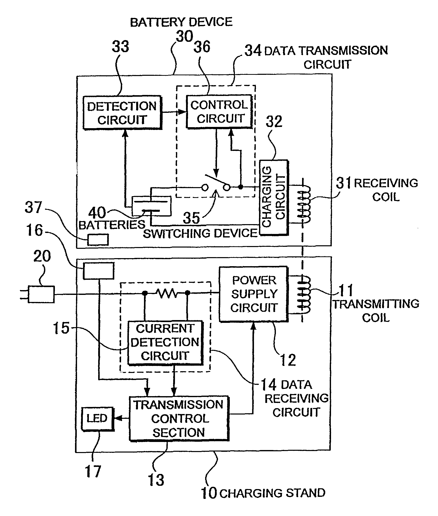
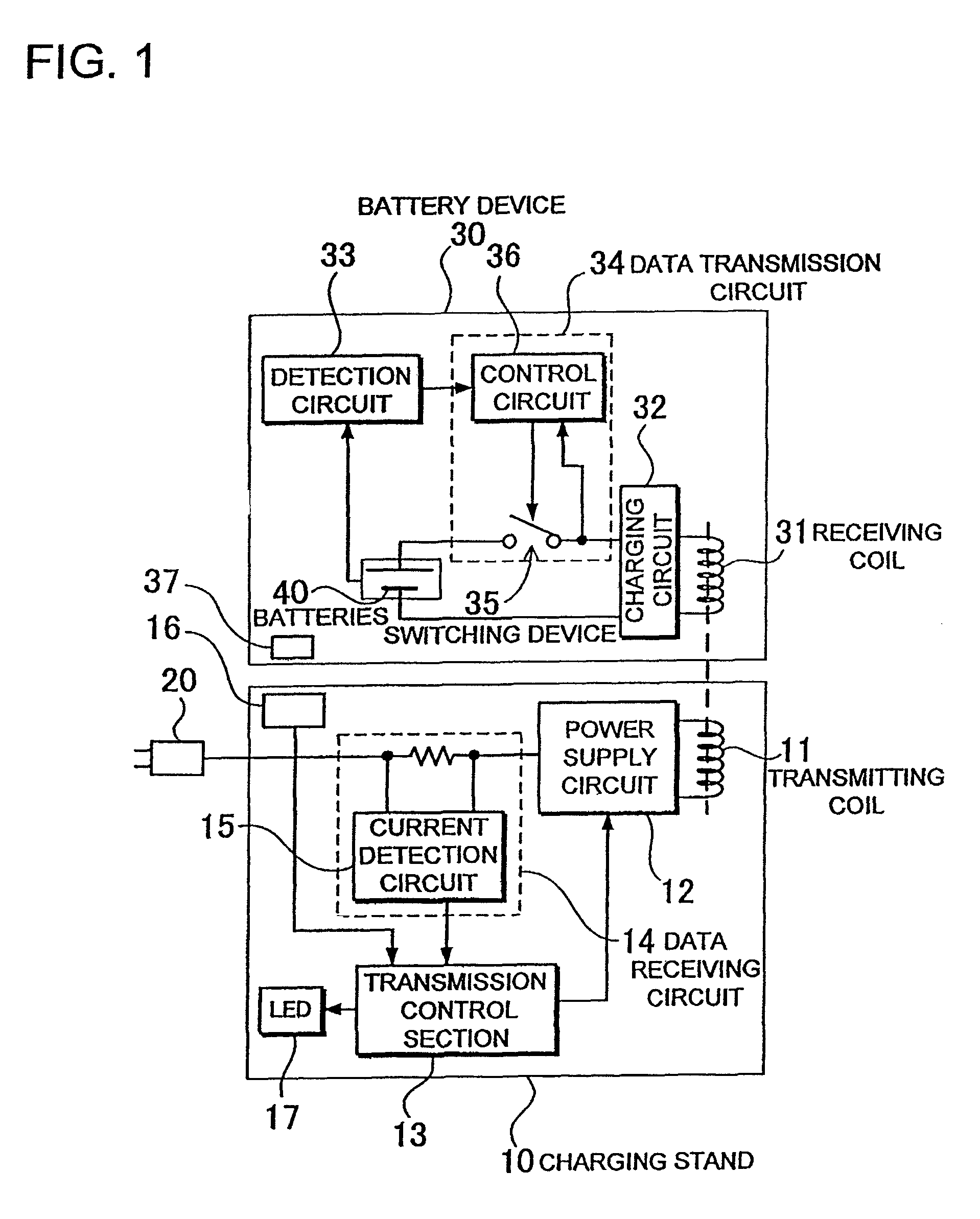
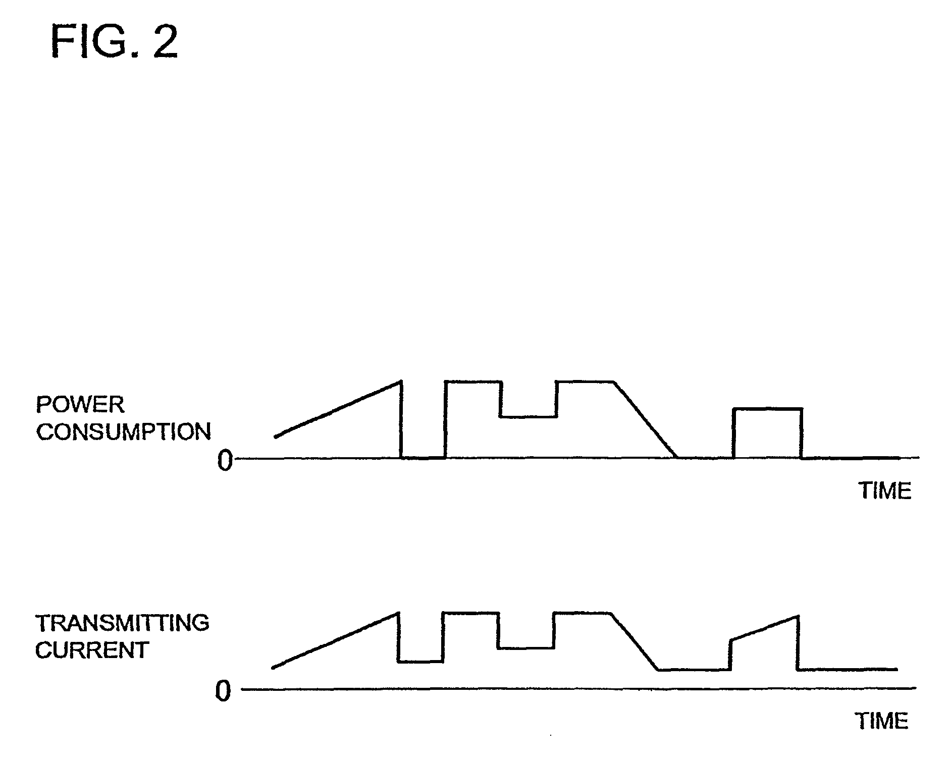
[0018]The method of data transmission embedded in electric power transmission can transmit data to the transmitting coil 11 side by changing the receiving coil 31 load in a specific pattern. In this data transmission method, various data can be accurately transmitted by varying the load in patterns specified beforehand.

[0019]The method of data transmission embedded in electric power transmission can transmit data between the receiving coil 31 side and the transmitting coil 11 side in an asynchronous fashion. Since data are transmitted asynchronously in this data transmission method, no circuitry is required to synchronize the receiving coil-side and the transmitting coil-side, and data can be transmitted with simple circuitry.

[0020]In the method of data transmission embedded in electric power transmission, batteries 40 can be charged with output from the receiving coil 31, and data indicating the state of charge of the batteries 40 can be transmitted from the receiving coil 31 side...


PUM


Abstract

The method of data transmission embedded in electric power transmission disposes a transmitting coil 11 and a receiving coil 31 in close proximity, transmits electric power in a non-contact fashion from the transmitting coil 11 to the receiving coil 31 by magnetic induction, and transmits data from the receiving coil 31 side to the transmitting coil 11 side. The method of data transmission changes the load on the receiving coil 31 and detects transmitting coil 11 current change corresponding to that load variation to send data from the receiving coil 31 side to the transmitting coil 11 side.

Description

BACKGROUND OF THE INVENTION[0001]1. Field of the Invention[0002]The present invention relates to a non-contact method of transmitting electric power from a transmitting coil to a receiving coil and in particular to a method of sending data from the receiving coil to the transmitting coil during power transmission, and to a charging stand and device housing batteries, which uses that data transmission method.[0003]2. Description of the Related Art[0004]A battery charging method and device that utilizes magnetic induction to transmit electric power from a transmitting coil to a receiving coil has been developed (refer to Japanese Laid-Open Patent Publication H09 -63655-A (1997) and Japanese Publication of Registered Utility Model Application No. JP 3011829-U). JP H09-63655-A describes a configuration having a charging stand that houses a transmitting coil magnetically excited by a high frequency power supply, and a battery pack that houses a receiving coil magnetically coupled with th...

Claims


Application Information

Patent Timeline
Patent Type & Authority Patents(United States)
IPC IPC(8): G08B21/00H02J7/00
CPCH02J7/025H02J7/00302H02J7/0045H02J50/90H02J50/80H02J50/40H02J50/10
Inventor YAMASHITA, TAKAHIRO
Owner KONINKLJIJKE PHILIPS NV
Why Eureka
Try Eureka