Machinery system allowing replacement of old reactor with a new reactor in nuclear power electric generating station

a technology of nuclear power electric generating station and machine system, which is applied in the direction of greenhouse gas reduction, way, and facility decommissioning, can solve the problems of unsafe and expensive situation for electric utilities and rate payers, and the inability of operating or decommissioned nuclear power electric generating stations to remove or replace their aging nuclear reactors

Inactive Publication Date: 2012-05-29
JUGL JOHN
View PDF6 Cites 2 Cited by
  • Summary
  • Abstract
  • Description
  • Claims
  • Application Information

AI Technical Summary

Problems solved by technology

At the present time, operating or decommissioned Nuclear Power Electric Generating Stations are unable to remove or replace their aging nuclear reactors.
This is an unsafe and expensive situation for the electric utility and the rate payers.

Method used


Image

  • Machinery system allowing replacement of old reactor with a new reactor in nuclear power electric generating station
  • Machinery system allowing replacement of old reactor with a new reactor in nuclear power electric generating station
  • Machinery system allowing replacement of old reactor with a new reactor in nuclear power electric generating station

Examples


Embodiment Construction

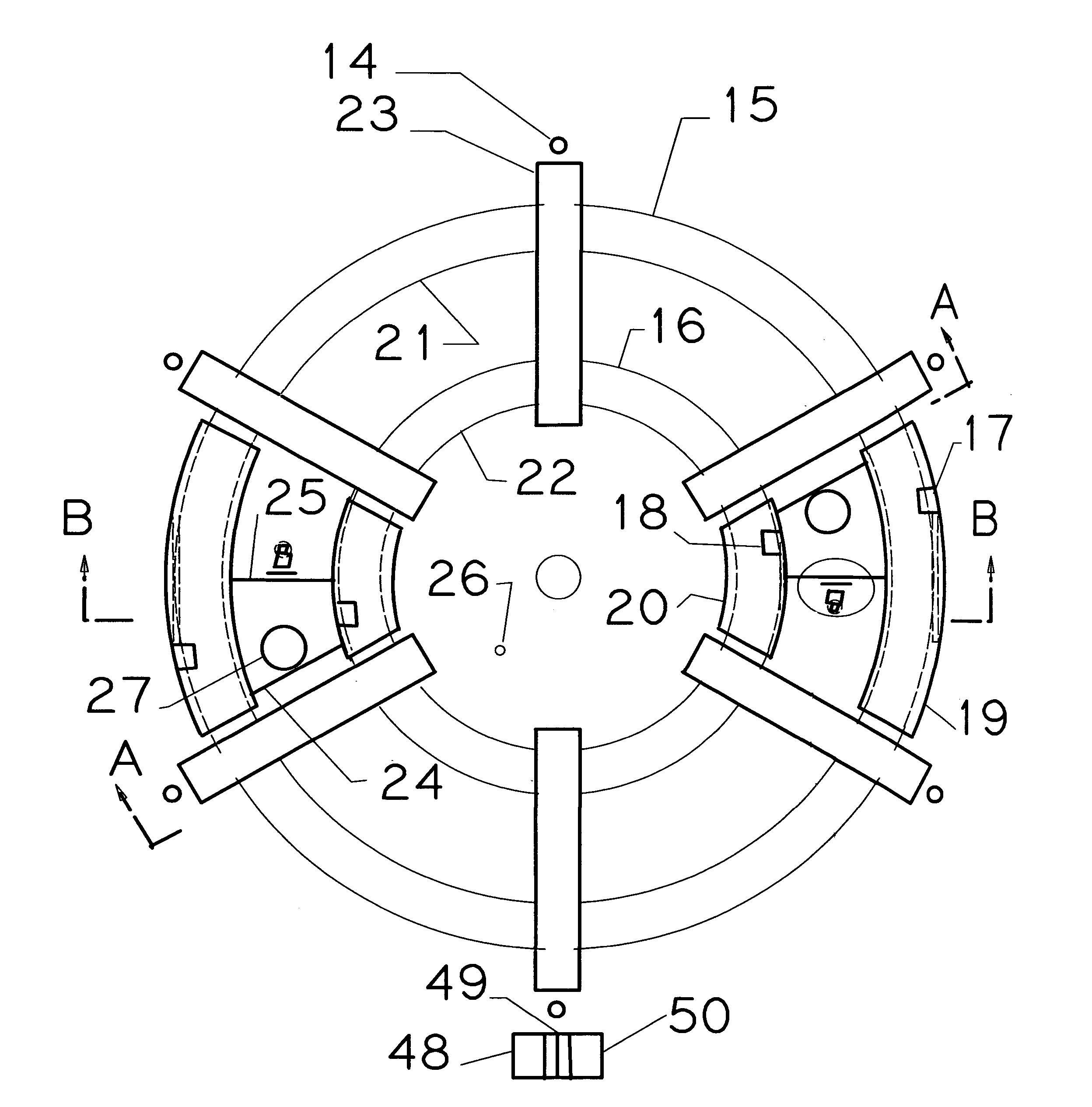
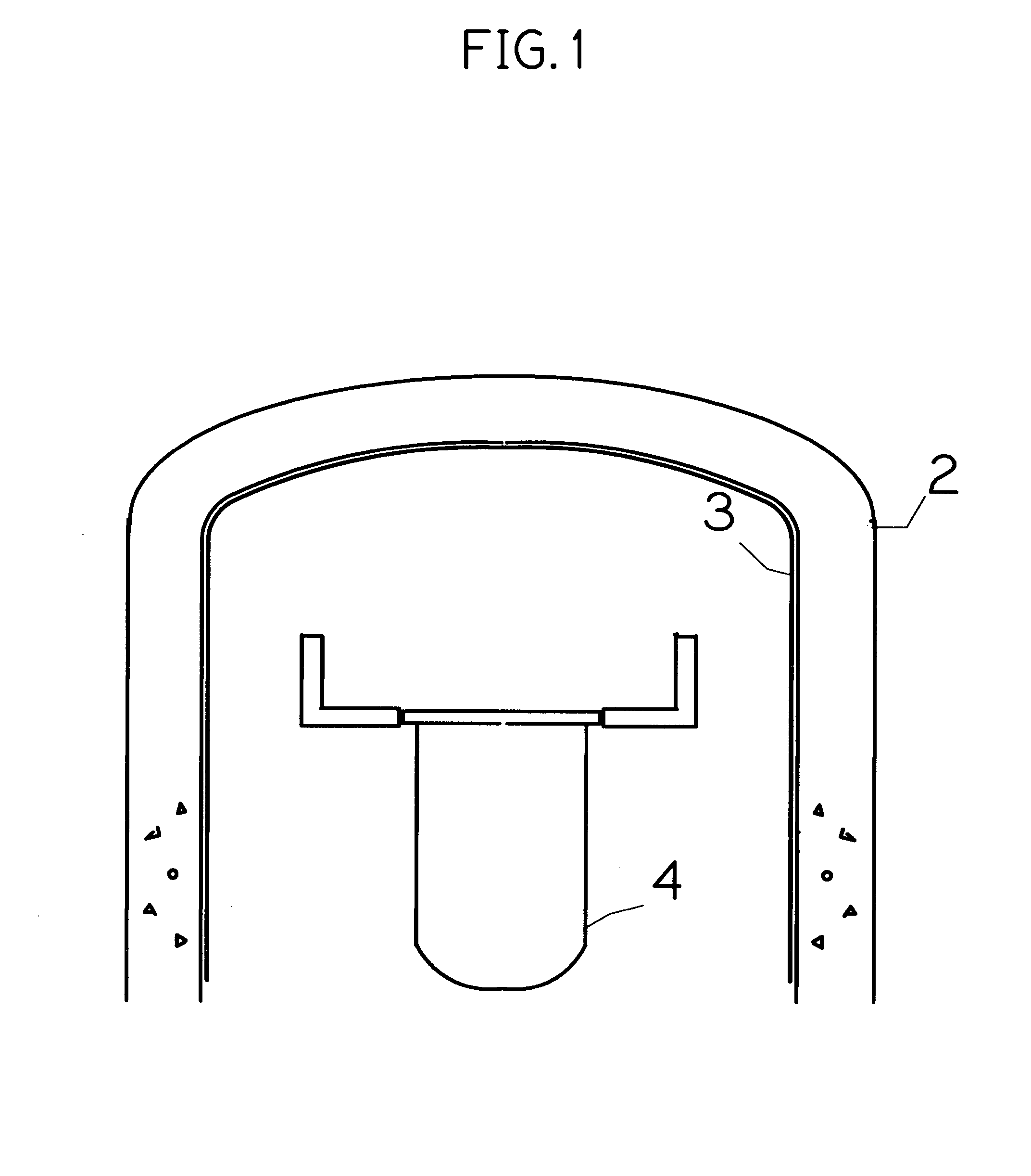
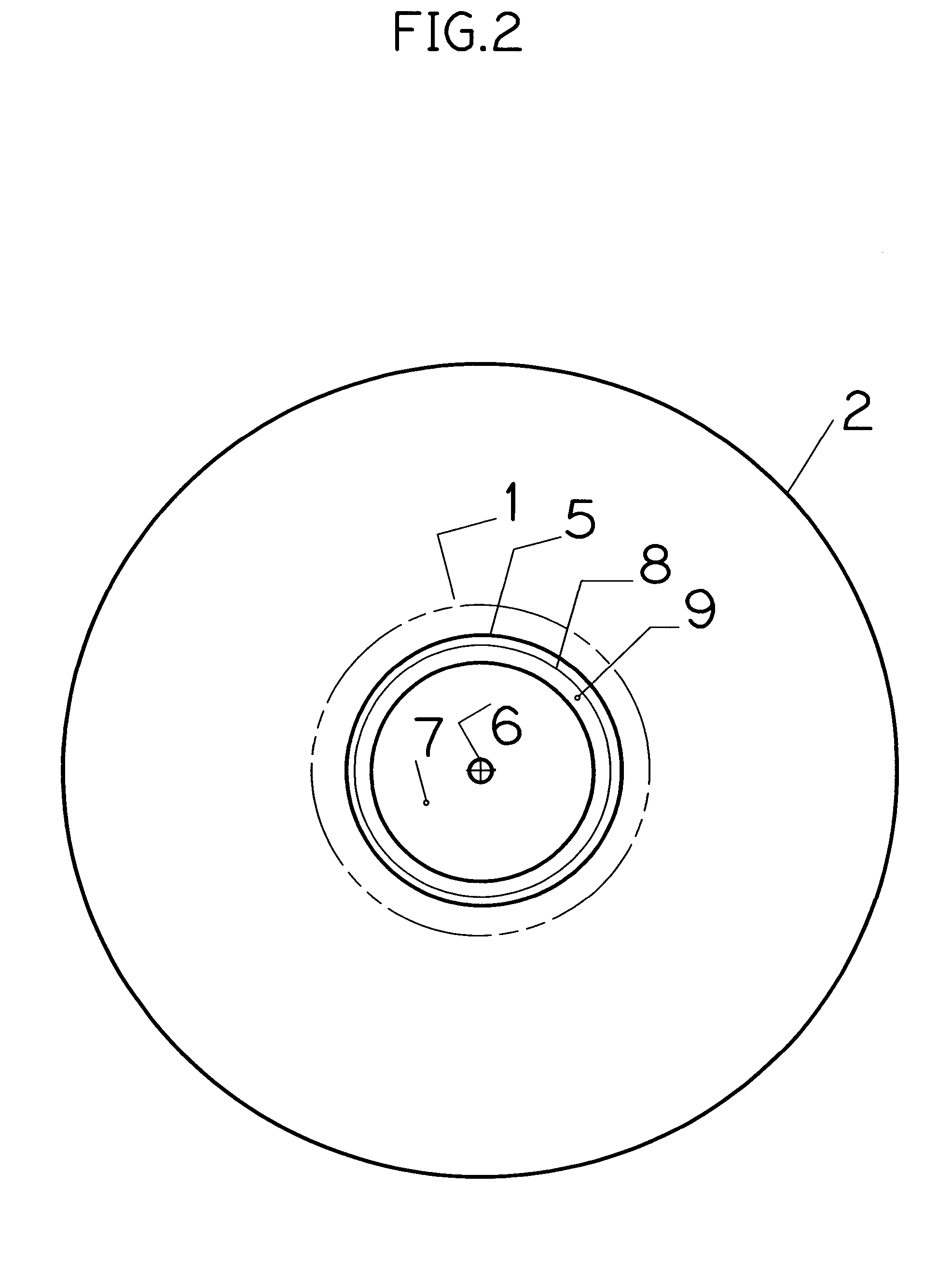
[0017]Description of the Dual Head Vertical Milling Machine (DHVMM), Application and Operating Procedure.

Overview and Location of Machine.

[0018]The work location of ((DHVMM) is on top of the Reactor Primary Containment (RPC) structure. Temporary scaffolding, working platform and elevator are built outside of the (RPC) to set up the work station. Interfering architectural sidings or steel if any, are removed. The (DHVMM) assembled and lifted from the ground level to the top of the (RPC) and secured with six anchor bolts. A standard industrial vacuum dust and debris collector machine is located on ground level. Two flexible suction hoses are connected to the work station near the cutting heads for dust and debris removal. FIG. 1 is a sectional view of the de-fueled, dismantled and decontaminated Reactor Pressure Vessel (RPV) 4, (RPC) 2 and the containment steel lining 3, prior to milling operation. FIG. 2 is a plain view, FIG. 3 is a sectional view after the milling operation is compl...


PUM

PropertyMeasurementUnit
diameteraaaaaaaaaa
diameteraaaaaaaaaa
diameteraaaaaaaaaa

Abstract

The machinery system and its application herewith, intended to create an opening in the roof of a Reactor Primary Containment of Generation II and III Nuclear Power Electric Generating Station. This opening is necessary to replace an aging nuclear reactor with a new, safer and more efficient reactor. Generation II and III Nuclear Power Electric Generating Stations include General Electric (GE) Boiling Water Reactor BWR / 2, 3, 4, 5 and BWR / 6 located in Mark II, and Mark III wet containments and Pressurized Water Reactors manufactured by Westinghouse, Combustion Engineering and Babcock and Wilcox located in dry containments. Until this time, existing reactor replacement was not possible due to Reactor Primary Containment structural enclosure configuration. The Dual Head Vertical Milling Machine System will remove a Reactor Primary Containment Dome Segment thus providing an opening, allowing reactor replacement and the electric generating station to remain operational for an other 40 years and beyond. Original containment integrity will be reinstated by closure of the opening.

Description

BACKGROUND OF THE INVENTION[0001]In a Nuclear Power Electric Generating Station most equipment no matter how small or large can be replaced with the exception of the Reactor. This is due to the Reactor Primary Containment inherent design configuration. The original design base was that after 40 years of useful operation, decommission the unit by entombing the Reactor in place in the Reactor Primary Containment. But, with today's world wide shortage of clean, renewable, affordable energy this approach is no longer practical or acceptable. The entire Generation II and III Reactors are rapidly reaching or exceeding their 40 years design life cycle. Some other phenomena such as the Inter Granular Stress Corrosion Cracking (IGSCC) may further reduce this life span. Scientific studies conducted by credible institutions such as the School of Materials, University of Manchester, U.K. and the Department of Chemical Engineering and Applied Chemistry, University of Toronto, Canada and many oth...

Claims


Application Information

Patent Timeline
Patent Type & Authority Patents(United States)
IPC IPC(8): G21C19/00
CPCG21C19/00G21C19/207G21D1/003Y02E30/40Y02E30/30Y02E30/00
Inventor JUGL, JOHN
Owner JUGL JOHN
Why Eureka
Try Eureka