Coffee machine with losing filter or capsule

a coffee machine and filter technology, applied in the field of coffee or espresso machines, can solve the problems of unreliable capsule filling/disposal system, water leakage and scaling inside the machine, and poor quality of the final product and a good clamping, so as to reduce the number of manual operations

Active Publication Date: 2012-06-05
SPINEL
View PDF6 Cites 13 Cited by
  • Summary
  • Abstract
  • Description
  • Claims
  • Application Information

AI Technical Summary

Benefits of technology

[0009]A semi-automatic, totally mechanical system to load and discard the disposable filer or capsule. The counterclockwise rotation, when closing, of the capsule by rotating the filter holder body, creates a housing geometrically fit for the capsule; the perfect overlap of the two bodies is guided by a grooving and tonguing joint and a ball pressed on the bottom of the rotating body that is housed inside a spherical cavity on the fixed body. During the coffee brewing, a vertical and ring joint stabilizes the two mechanical parts and allows a perfect and rigid grasp between the two bodies, balancing the high pressures during the brewing. This implies a perfect housing of the capsule and avoids possible deformations produced by the combined effect, by the type of plastic material, and by the high working pressure and water temperatures. The rear sensor rod and the front gravity extractor are positioned in a way to ensure, once the brewing is over, the removal of the used capsule that is discarded into a small container located on the bottom of the machine chassis. While brewing, in fact, the capsule could adhere to the housing surfaces in case it is deformed by pressure and temperature. After the removal, the device is automatically ready to receive a new capsule manually inserted for the next brewing. The system is solid, reliable, and allows to repeat the placement and removal of the capsule with a rotation of 60° of the rotating part.
[0010]A full mechanical clamping system of the capsule infusion piston operated in conjunction among the pressure cam, the tappet, the heat exchanger and the infusion piston, has a double function: to clamp the piston and to feed the electric circuit of the electro-pump with a synchronized system comprising a brewing cam connected to the motor shaft, which activates a micro-switch. In fact, only when the capsule is on its place, the electro-motor starts rotating, clockwise, of 180°; it drags the pressure cam and, at the same time, lowers the brewing cam which insure, by its synchronized position, that the capsule is pressed and, at the same time, sets in motion the electro-pump and the brewing. This system allows to conserve the total working power of the electro-pump for the brewing effort, ensuring an excellent coffee, no water leakage and absence of scaling or premature wear of the mechanisms.
[0011]A double possibility to adjust the distance between the capsule and the piston. This is achieved by a macro-regulation by mean of the piston rotation (clockwise or counterclockwise), increasing or decreasing the distance from the capsule, as a macro-regulation; a micro-regulation by mean of the tappet sliding inside the housing shaped on the heat exchanger, controlled by two Belleville washers and limited by a threaded dowel. This regulation allows an accurate adjustment to compensate for possible flaw of the capsule.
[0012]An electro-mechanical control system to verify that the capsule is properly lodged and verifies the lodging pressure of the brewing piston. This guarantees that the machine works under these conditions, thus reducing the number of manual operations is reduced.

Problems solved by technology

Such a pressure distribution among three systems, however, does not allow a good quality of the final product and a good clamping pressure, producing water leakage and scaling inside the machine.
Moreover, the capsule filling / disposal system is rather complex and unreliable for it uses a spring mechanism, which is likely to loose the original mechanical features due to the use and high temperatures.

Method used


Image

  • Coffee machine with losing filter or capsule
  • Coffee machine with losing filter or capsule
  • Coffee machine with losing filter or capsule

Examples


Embodiment Construction

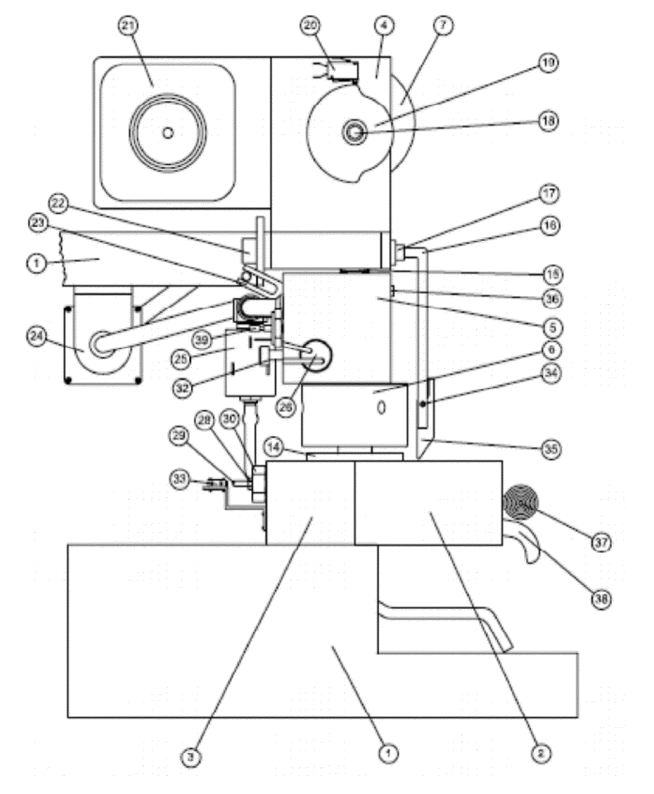
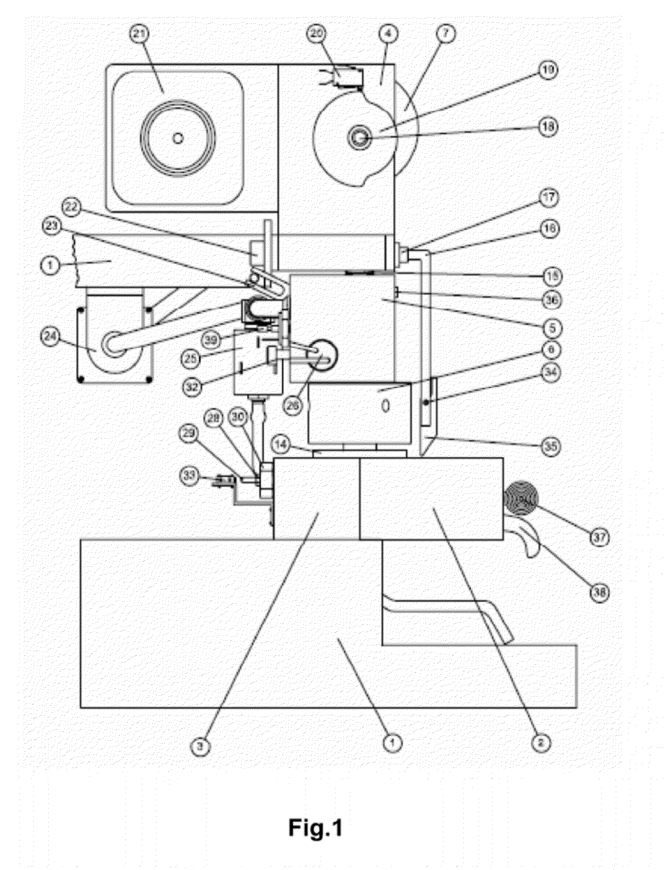
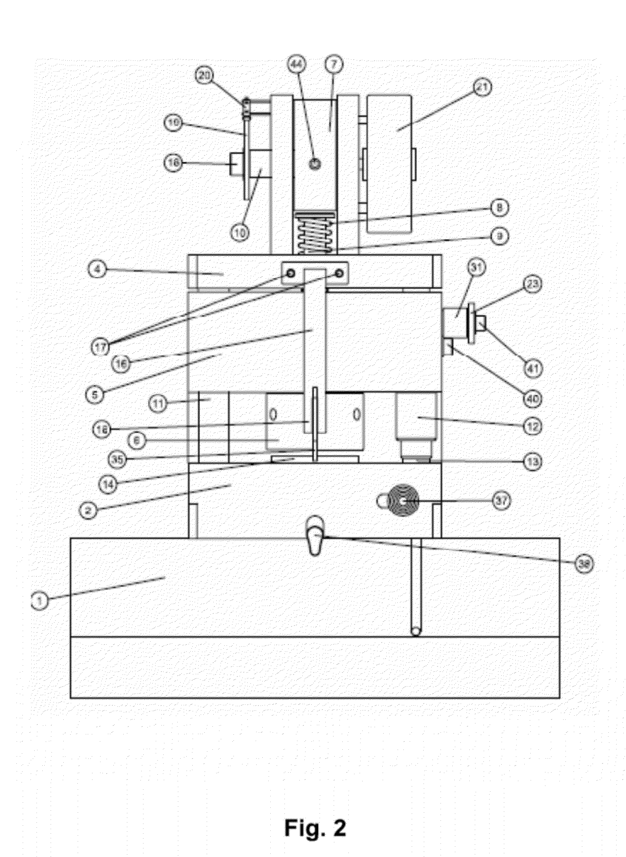
[0024]Referring to the drawings, and particularly to FIGS. 1, 2 and 3, the espresso machine consists of a chassis 1, a capsule-holder body comprising a rotating part 2 and a fixed part 3, equipped with a knob 37, a brewing spout 38, a sensor shaft 29, a micro-switch 33 and front extractor 35 which can lodge a disposable filter or capsule 14, a heat exchanger 5, with electro-pump 24, electro-valve for water delivery 25, a heater 26 and thermostat 39, a piston 31 and related ciclers 43, tappet 9 and an accelerator 31, a pressure cam 7, and a coffee brewing cam 19 with micro-switch 20, both controlled by an electro-motor 21, supporting means, fixing means, regulation and sealing means.

[0025]With the machine in stand-by, the pressure cam 7 is at the top dead center (Phase A in FIG. 5). This cam connected to the motor shaft 10 by means of a threaded dowel 44 rotates inside the motor flask 4; on the same shaft the coffee brewing cam 19 is connected by means of a screw 18.

[0026]By means of...


PUM


Abstract

An espresso machine using an innovative, semi-automatic, mechanical system to load and discard the disposable coffee filter or capsule, comprising a novel system of sealing and applying pressure on the disposable filter or capsule to avoid spurts of coffee or hot water while the coffee is brewed, consisting of a completely mechanical clamping system of sealing between the capsule and the infusion piston by manually adjusting the distance between the capsule and the piston and the use of an electro-mechanical control system to verify that the capsule is properly lodged and to verify the lodging pressure of the brewing piston.

Description

RELATED APPLICATIONS[0001]The application is a U.S. National Stage application according to 35 U.S.C. 371 of PCT / IT2007 / 000173 application filed on 8 Mar. 2007.[0002]The applications claims foreign priority according to 35 USC 119(e) on Italian patent application LE2006A000009 filed on Mar. 10, 2006.TECHNICAL FIELD[0003]The present invention relates to a coffee or espresso machine using a disposable filter or capsule, equipped with a semi-automatic system operating in two phases:[0004]1) Manual placement of the disposable filter or capsule;[0005]2) Coffee brewing and return to phase 1 by electronic control and electro-mechanical actuators.[0006]Espresso machines of this type use a special one-cup semi-rigid plastic filter, which contains grounded, dosed and tamped coffee, also referred as disposable filter or capsule. Hereafter it will be identified as capsule. In the espresso machines on the market the same pump generally operates the hydraulic clamping system, the automatic dispos...

Claims


Application Information

Patent Timeline
Patent Type & Authority Patents(United States)
IPC IPC(8): A47J31/40
CPCA47J31/0668A47J31/36A47J31/368A47J31/4471G07F13/065
Inventor SPINELLI, GIOVANNI
Owner SPINEL
Why Eureka
Try Eureka