Multi-path evaporative purge system for fuel combusting engine

a technology of evaporative purge and combustion engine, which is applied in the direction of combustion air/fuel air treatment, machines/engines, instruments, etc., can solve the problems of limited engine shutdown time, and limited extent to which the purge valve can be opened, so as to improve the fuel efficiency of the engine and increase the engine off time

Inactive Publication Date: 2012-06-05
FORD GLOBAL TECH LLC
View PDF18 Cites 11 Cited by
  • Summary
  • Abstract
  • Description
  • Claims
  • Application Information

AI Technical Summary

Benefits of technology

[0002]As one approach, the inventors have provided herein a method of operating an evaporative purge system for an engine of a vehicle propulsion system, comprising during a first condition, loading at least a first fuel vapor storage canister with fuel vapors (e.g. during a refueling event); during a second condition, purging fuel vapors stored by at least the first canister to the engine; during a third condition, loading a second fuel vapor storage canister with fuel vapors without loading the first canister with fuel vapors; and during a fourth condition, purging fuel vapors stored by the second canister to the engine without purging fuel vapors from the first canister. By independently loading and unloading the canisters in response to operating conditions, engine off time may be increased, at least under some conditions, thereby improving fuel efficiency of the engine.
[0003]As a first embodiment, an evaporative purge system for an engine of a vehicle is provided. The system comprises a fuel tank configured to store a fuel; a first canister configured to store a vapor state of the fuel; a second canister configured to store the vapor state of the fuel; a first vapor passage coupling the fuel tank to the first canister; a first valve arranged along the first vapor passage configured to control the flow of vapor through the first vapor passage; a second vapor passage coupling the second canister to the first vapor passage between the first valve and the fuel tank; a third vapor passage coupling the first canister to an intake air passage of the engine; a second valve arranged along the third vapor passage configured to control the flow of vapor through the third vapor passage; a fourth vapor passage coupling the second canister to the third vapor passage between the second valve and the intake air passage; a fifth passage having a first end coupled to the first canister and a second end communicating with ambient; a third valve arranged along the fifth passage configured to control flow through the fifth passage; a sixth passage having a first end coupled to the second canister and a second end communicating with the fifth passage between the third valve and the first canister; and a fourth valve arranged along the third passage between where the fourth passage is coupled to the third passage and the engine, wherein the fourth valve is configured to control flow through the third passage. In this way, vapors may be supplied to or purged from each canister via separate flow paths, thereby providing independent control of the loading and unloading of the canisters.
[0004]As a second embodiment, an evaporative purge system for an engine of a vehicle is provided. The system comprises a fuel tank configured to store a fuel; a first canister configured to store a vapor state of the fuel; a second canister configured to store the vapor state of the fuel; a first vapor passage coupling the fuel tank to the first canister; a first valve arranged along the first vapor passage configured to control the flow of vapor through the first vapor passage; a second vapor passage coupling the first canister to the second canister; a second valve arranged along the second passage configured to control the flow of vapor through the second vapor passage, wherein the second valve is a three-way valve; a third vapor passage coupling the first passage to the second passage, wherein the third passage is coupled to the second passage via the three-way valve; a fourth passage having a first end coupled to the second canister and a second end communicating with ambient; a third valve arranged along the fourth passage configured to control flow through the fourth passage; a fifth vapor passage having a first end coupled to the first canister and a second end coupled to an intake passage of the engine; a fourth valve arranged along the fifth vapor passage configured to control the flow of vapor through the fifth vapor passage; and a sixth vapor passage having a first end coupled to the second canister and a second end coupled to the fifth vapor passage between the first canister and the fourth valve. In this way, vapors may be supplied to or purged from each canister via separate flow paths, thereby providing independent control of the loading and unloading of at least the second canister.

Problems solved by technology

Some hybrid vehicle propulsion systems are limited by the available manifold vacuum levels or the duration of time that the engine may be deactivated during operation of the vehicle, such as with some hybrid electric vehicles.
Since the evaporative canister is typically purged while the engine is performing combustion in order to utilize the stored fuel vapor for combustion, the amount of time the engine can be turned off may be limited in part by the mass of fuel vapor to be purged from the canister.
Furthermore, some evaporative purging systems may also experience difficulty purging fuel vapor from the canister due to excessive vacuum in the fuel tank, thereby limiting the extent to which the purge valve can be opened.
For example, the restriction caused by a relatively large evaporative emissions canister configured to store both refueling vapors and diurnal vapors or other system losses may cause a relatively large pressure drop, thereby creating a vacuum on the fuel tank.

Method used


Image

  • Multi-path evaporative purge system for fuel combusting engine
  • Multi-path evaporative purge system for fuel combusting engine
  • Multi-path evaporative purge system for fuel combusting engine

Examples


first embodiment

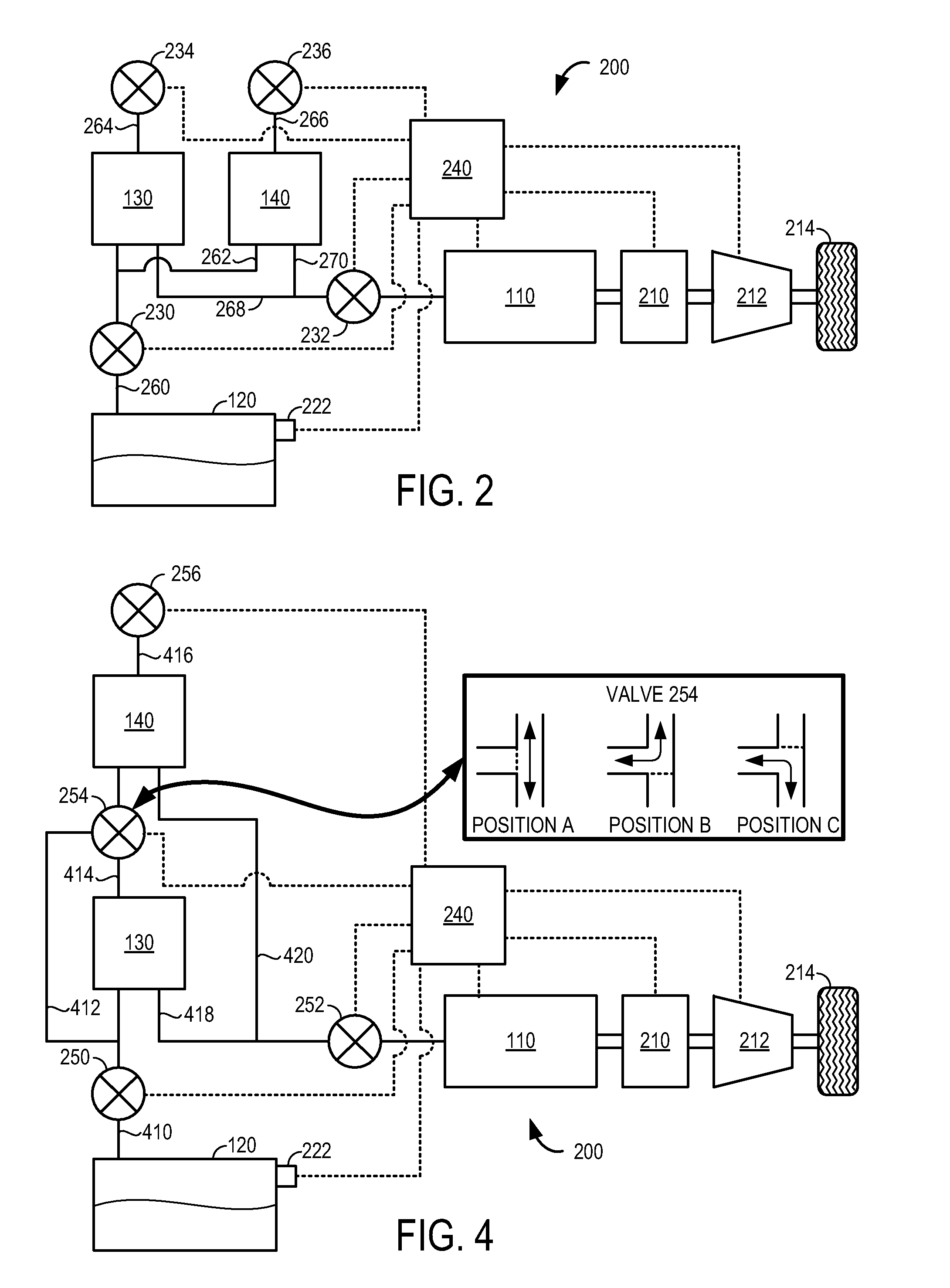
[0016]The first embodiment, which is described with reference to FIGS. 2 and 3, includes a second canister vent valve. With two canister vent valves in the system the control system can control which path the vapors will flow (i.e. through canister 130 or canister 140). These two canister vent valves can then also be used to select which canister fuel vapors will be purged. During an emissions cycle canister 140 can be substantially purged of fuel vapors before purging canister 130.

second embodiment

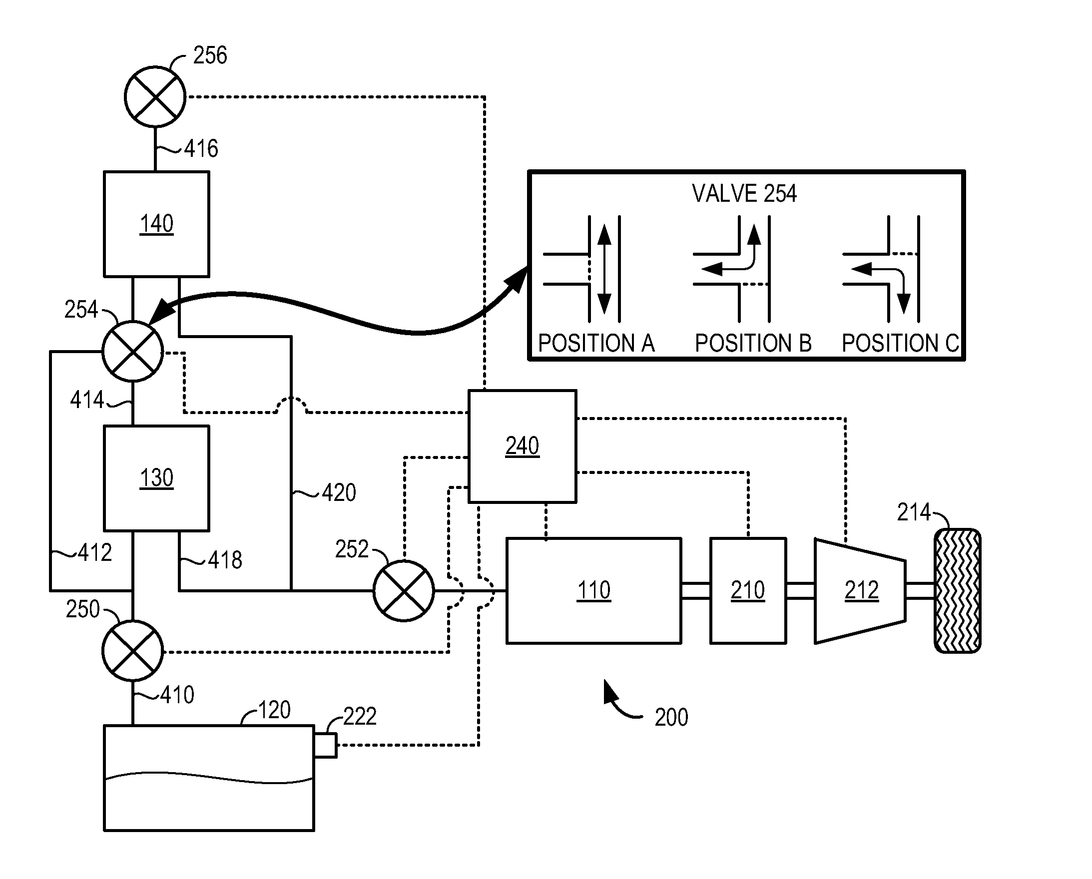
[0017]The second embodiment, which is described with reference to FIGS. 4 and 5, includes a three-way valve arranged between canister 130 and canister 140, thus allowing the flow to be directed through only canister 140 or through both canisters 130 and 140. In a similar fashion, this three-way valve can then also be actuated to partition the purge flow in order to substantially purge canister 140 of fuel vapors before purging canister 130.

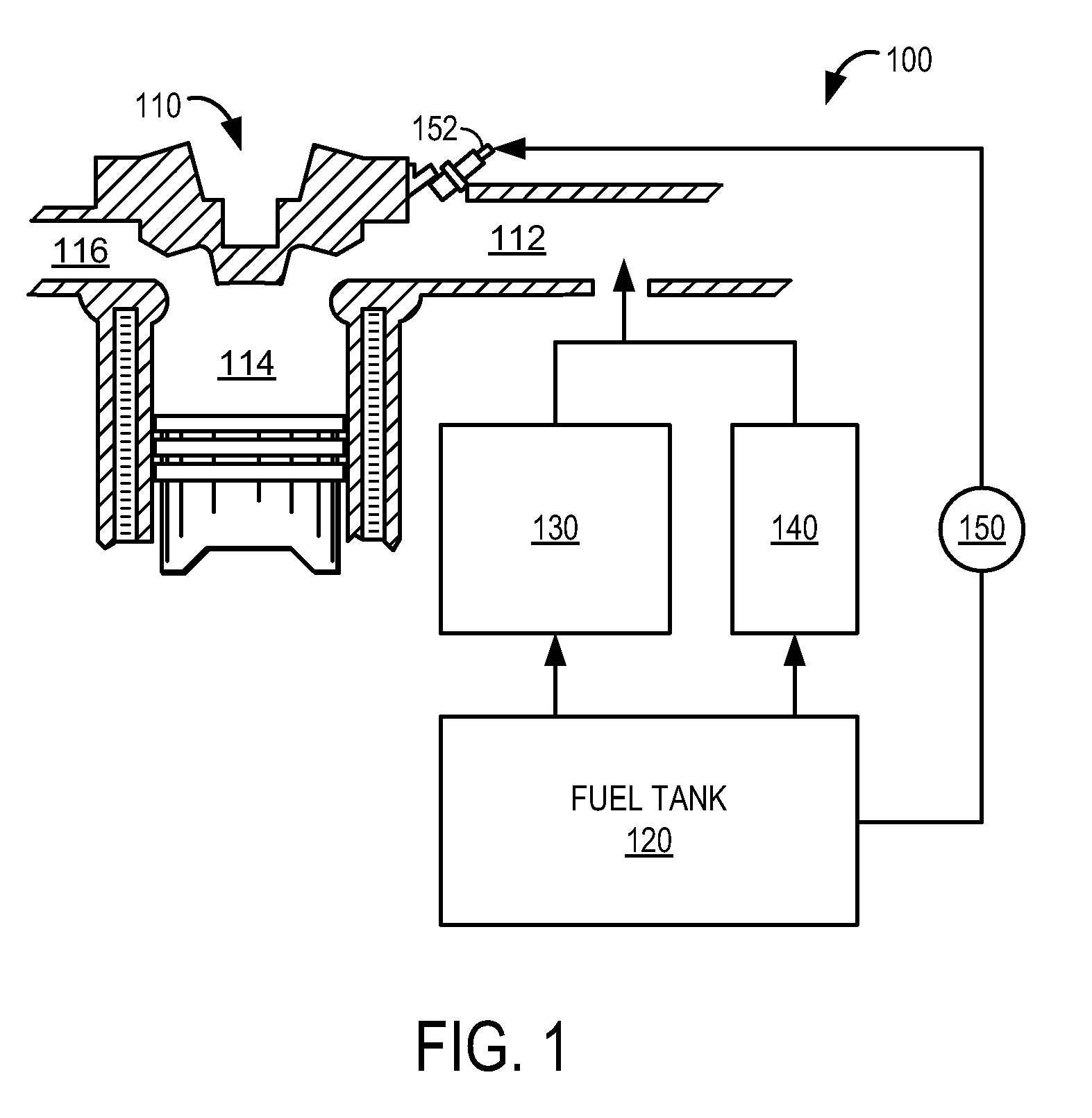
[0018]FIG. 2 shows a first embodiment of an evaporative purge system for a vehicle propulsion system 200. In this particular embodiment, propulsion system 200 is configured as a hybrid electric vehicle (HEV) including engine 110 and electric motor 210. One or more of engine 110 and electric motor 210 may be operatively coupled to at least one vehicle drive wheel 214 via a transmission 212. For example, where propulsion system 200 is configured as a series HEV, engine 110 may be operated to recharge an energy storage device such as an electric batt...

third embodiment

[0038]FIG. 7 shows a flow chart depicting an example routine for controlling the evaporative purge system. Note that some or all of the valves may be operated by control system 240 as directed by the routine shown in FIG. 7, while some of the valves may be actuated without direct actuation by the control system. For example, some of the valves may be operated as directed by the routine of FIG. 7 based on pressure differences across the valve or by actuators directly linked to the valve.

[0039]At 710 it may be judged whether the engine is on, for example, as described with reference to 310. If the answer at 710 is no, it may be judged at 712 whether the refueling trigger is activated, for example, as described with reference to 312. If the answer at 712 is yes, valve 630 may be opened at 714, valve 636 may be opened at 716, and valves 632 and 634 may be closed at 718 to enable fuel vapors to be stored by at least canister 130 at 720. It should be appreciated that the configuration of ...


PUM


Abstract

A method of operating the evaporative purge system for an engine of a vehicle propulsion system is provided. In one example, the method provides for charging and purging two fuel vapor canisters independently or at the same time. The method may provide for improved fuel vapor processing under some conditions.

Description

BACKGROUND AND SUMMARY[0001]Some hybrid vehicle propulsion systems are limited by the available manifold vacuum levels or the duration of time that the engine may be deactivated during operation of the vehicle, such as with some hybrid electric vehicles. Since the evaporative canister is typically purged while the engine is performing combustion in order to utilize the stored fuel vapor for combustion, the amount of time the engine can be turned off may be limited in part by the mass of fuel vapor to be purged from the canister. As one example, the fuel vapor storage canister may be cleaned by purging the canister at least once each drive cycle or once per each fuel tank refueling so that fuel vapor break through does not occur. Furthermore, some evaporative purging systems may also experience difficulty purging fuel vapor from the canister due to excessive vacuum in the fuel tank, thereby limiting the extent to which the purge valve can be opened. For example, the restriction cause...

Claims


Application Information

Patent Timeline
Patent Type & Authority Patents(United States)
IPC IPC(8): F02M33/02
CPCF02M25/0836F02M25/089
Inventor DEVRIES, JASON EUGENEPETERS, MARK WILLIAM
Owner FORD GLOBAL TECH LLC
Why Eureka
Try Eureka