
Detecting photons in the presence of a pulsed radiation beam

a radiation beam and detection system technology, applied in the field of radiation detection systems, can solve the problems of reducing the sensitivity of radiation detectors that have long dead times, such as geiger-muller and proportional counters, and suggesting the use of fluoroscope images during actual beam therapy. , to achieve the effect of reducing interference or avoiding interferen

Inactive Publication Date: 2012-06-05
NAVOTEK MEDICAL
View PDF27 Cites 19 Cited by
  • Summary
  • Abstract
  • Description
  • Claims
  • Application Information

AI Technical Summary

Benefits of technology

"The invention is about a system for treating a body with a pulsed beam of ionizing radiation while using a detector system to monitor the treatment in real-time. The detector system is designed to reduce interference from the beam and make the sensitivity of the detector lower during the pulses of the beam. The data record created by the detector system selectively excludes data for the radiation received during the pulses of the beam. This allows for the creation of a record that is less affected by interference and provides information on the motion and position of the body being treated. The detector system can be a scintillation detector or a tracking system, and the control circuitry can adjust the position of the beam or reduce the power of the beam in response to the difference between the planned and actual position of the treatment target."

Problems solved by technology

But they do not suggest the use of such fluoroscope images during actual beam therapy, instead using index markers or other known methods of gating to respiration.
U.S. Pat. No. 6,865,411 states that it is a disadvantage that imaging and radiation beam therapy cannot be done at the same time.
Radiation detectors that have long dead times, such as Geiger-Muller and proportional counters, tend to become saturated at such high peak intensities, and are not suitable for safety monitoring of radiation levels outside rooms where linacs are used.

Method used


Image

  • Detecting photons in the presence of a pulsed radiation beam
  • Detecting photons in the presence of a pulsed radiation beam
  • Detecting photons in the presence of a pulsed radiation beam

Examples


Embodiment Construction

[0069]The present invention, in some embodiments thereof, relates to radiation detection systems used in the vicinity of pulsed radiation beams and other radiation sources, and, more particularly, but not exclusively, to x-ray and gamma-ray imaging and tracking systems used to monitor patients while they are treated by pulsed radiation therapy beams.

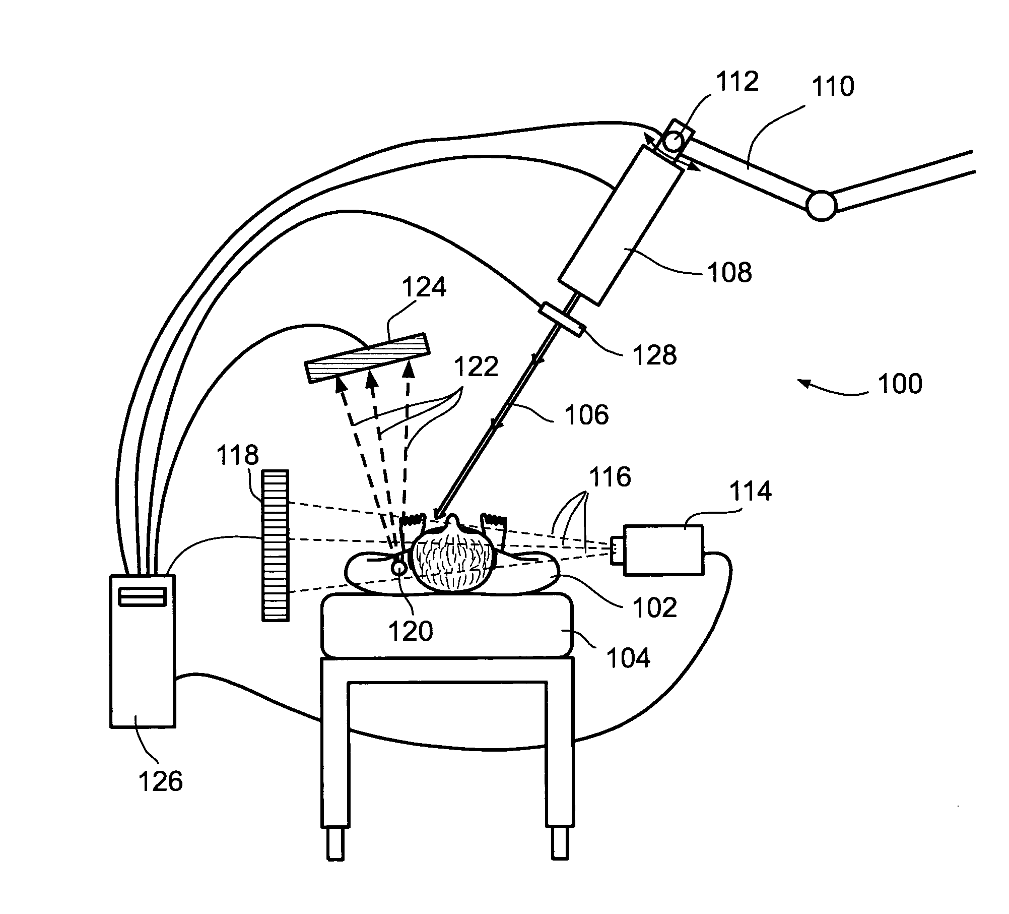
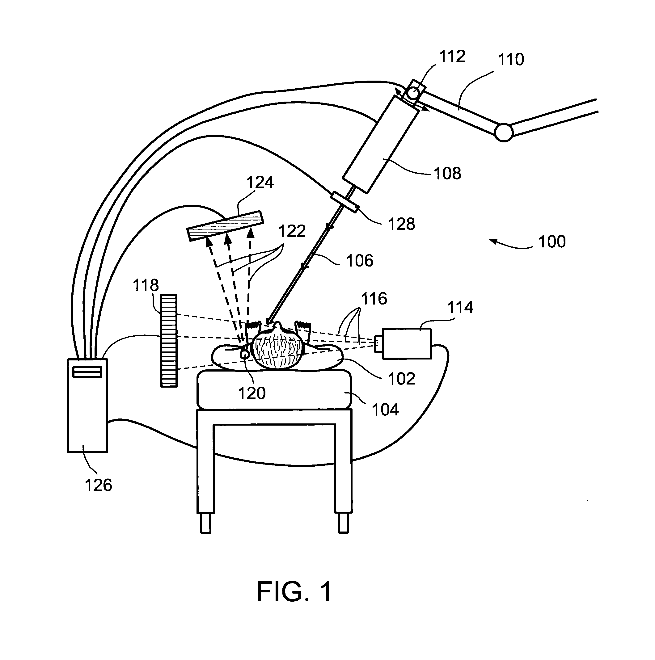
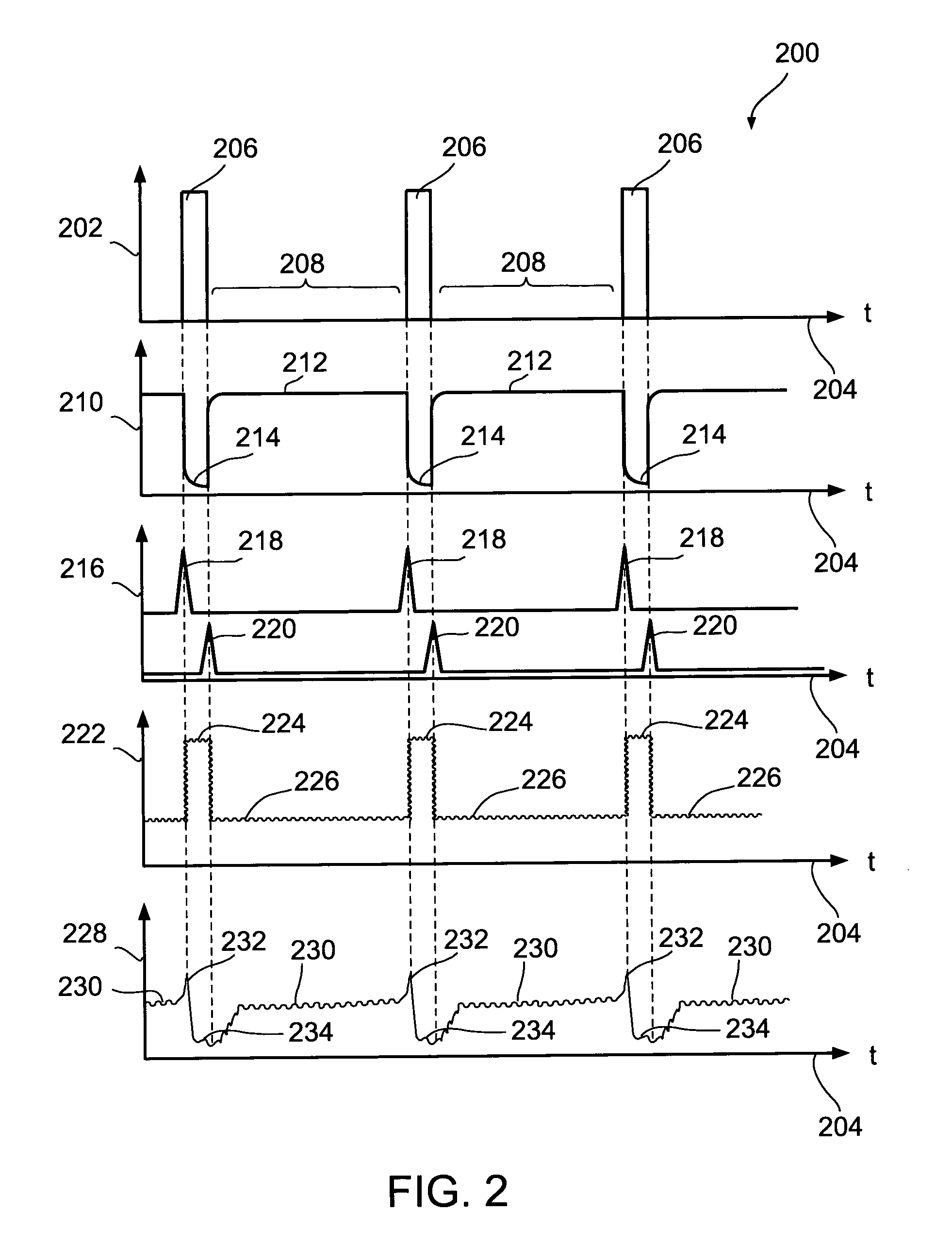
[0070]An aspect of some embodiments of the invention concerns a radiation treatment system that uses a pulsed beam of radiation to treat a body, with pulse lengths and intervals between pulses shorter than 100 milliseconds, together with a detector system that uses another source of radiation to monitor the body during the treatment. In an exemplary embodiment of the invention, the detector system reduces or avoids interference from the beam by having reduced sensitivity during the pulses, or not recording data for radiation detected during the pulses, and recording data for radiation detected in the intervals between pulses.

[0071]Option...


PUM


Abstract

A detector system adapted for monitoring a radiation treatment system comprising a pulsed beam radiation source for treating a body with a given beam intensity and beam configuration, with pulse times and intervals between pulses less than 100 milliseconds, using at least one monitoring radiation source located inside or outside the body, the detector system comprising; a) a detector designed to detect radiation from the monitoring source, and subject to interference radiation from the beam source; and b) control circuitry that creates a data record of radiation received by the detector, to provide information about the body; wherein, when the detector detects radiation in real time during operation of the beam, the data record selectively excludes data for radiation received by the detector during the pulses, as opposed to data for radiation received by the detector between pulses.

Description

RELATED APPLICATIONS[0001]This application claims benefit under 35 USC 119(e) from U.S. provisional patent application 60 / 992,691, filed on Dec. 5, 2007.[0002]The contents of all of the above documents are incorporated by reference as if fully set forth herein.FIELD AND BACKGROUND OF THE INVENTION[0003]The present invention, in some embodiments thereof, relates to radiation detection systems used in the vicinity of pulsed radiation beams and other radiation sources; and, more particularly, but not exclusively, to x-ray and gamma-ray imaging and tracking systems used to monitor patients while they are treated by pulsed radiation therapy beams.[0004]Radiation therapy is often used to treat cancer and other abnormal growths. Such therapy can use implanted radioactive sources (brachytherapy), or external radiation sources, generally beams, including x-ray beams and electron beams produced by linacs, as well as proton beams and heavy ion beams. Such beams are also used for radiosurgery, ...

Claims


Application Information

Patent Timeline
Patent Type & Authority Patents(United States)
IPC IPC(8): G21K1/02
CPCA61B6/4258A61N5/1049A61B2019/542A61N2005/1061A61B2090/392
Inventor SHCHORY, TALKORNBLAU, GIORANEUSTADTER, DAVID MAIERSTOKAR, SAUL
Owner NAVOTEK MEDICAL
Learn More