
Photovoltaic solar roof tile assembly system

a solar roof and solar panel technology, applied in the direction of photovoltaics, solar heat collectors for particular environments, heat collector mounting/support, etc., can solve the problems of not providing a solution to simplifying the installation of photovoltaic systems, the photovoltaic panel assembly is accomplished either by mechanical fasteners, and the installation method is not provided. , to achieve the effect of effective integration of photovoltaic cells and high flexibility of design

Active Publication Date: 2012-06-12
SR CONSULTING
View PDF33 Cites 36 Cited by
  • Summary
  • Abstract
  • Description
  • Claims
  • Application Information

AI Technical Summary

Benefits of technology

"The patent text describes a new system for roofing and other structures that combines a composite material tile and a photovoltaic cell. The system is designed to be simple and modular, and can be easily installed on existing structures. The use of composite materials and high precision molding processes allows for a tight and robust fit, and a sealable tile to tile interlocking system to prevent water ingress. The system is also more flexible and design-friendly than traditional roofing products. The use of a track system makes the installation process easier and safer, and the system can be easily integrated with existing structures. Overall, the system provides an effective and modular solution for combining photovoltaic cells with roofing or other structures."

Problems solved by technology

While these alternative materials compensate for the weaknesses of the traditional designs, such as dimensional instability, weight, and environmental concerns, they do not provide a solution to problems associated with traditional installation methods.
An apparent disadvantage to the rail systems is that the assembly of the photovoltaic panels is accomplished either with mechanical fasteners or chemical bonding.
The electrical wiring of these systems are traditional wiring harnesses and connectors, and do not provide a solution to simplifying the installation of the photovoltaic systems to a building structure.
While this system provides a solution for electrical interconnectivity of photovoltaic panels, it does not provide a structural fastening system for photovoltaic roof tiles.

Method used


Image

  • Photovoltaic solar roof tile assembly system
  • Photovoltaic solar roof tile assembly system
  • Photovoltaic solar roof tile assembly system

Examples


Embodiment Construction

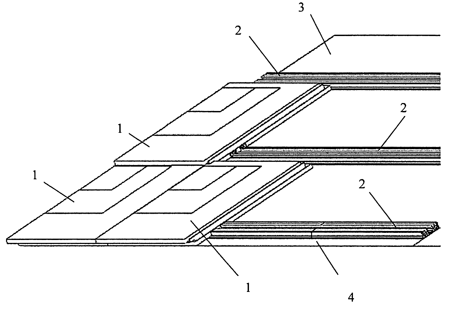
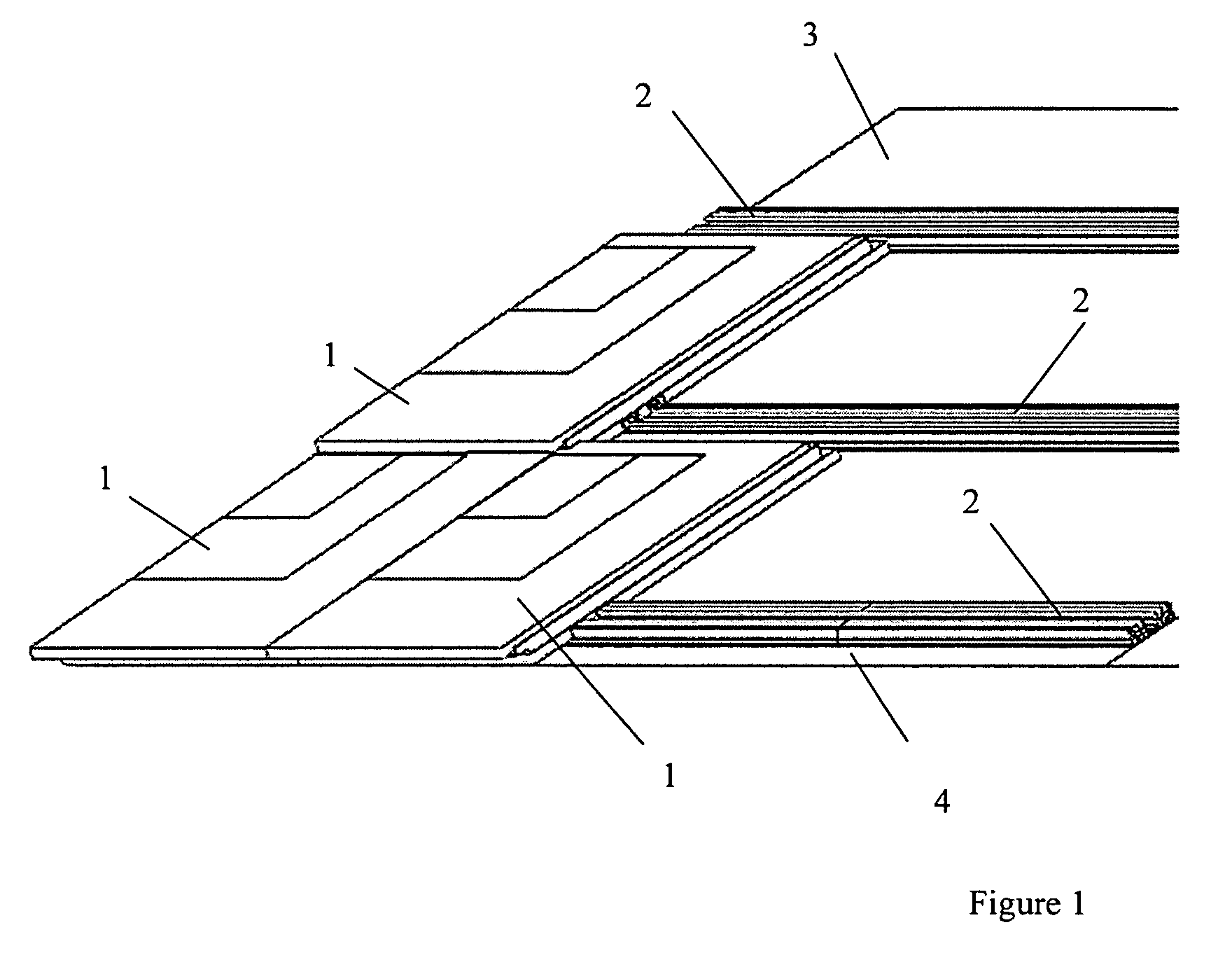
[0027]As shown in FIG. 1, a number of tiles (1) are affixed to a roofing structure (3) using a track system (2). The track system is either nailed or screwed to the roof structure, in locations marked by the installer to position the composite tiles vertically. Pre-cut lengths of track can be installed beside each other to form one continuous length of track by butting the track together (4) and fastening each free end down. Alternatively, a clip connector as would be known in the art may be designed to secure the ends of mating track to each other. The tiles are snapped into place on the extruded track and can be removed or slid along the longitudinal direction of the track. Adjacent tiles advantageously overlap each other as shown in FIG. 1. A sufficient number of tiles and track are assembled to the roofing structure to achieve the coverage desired.

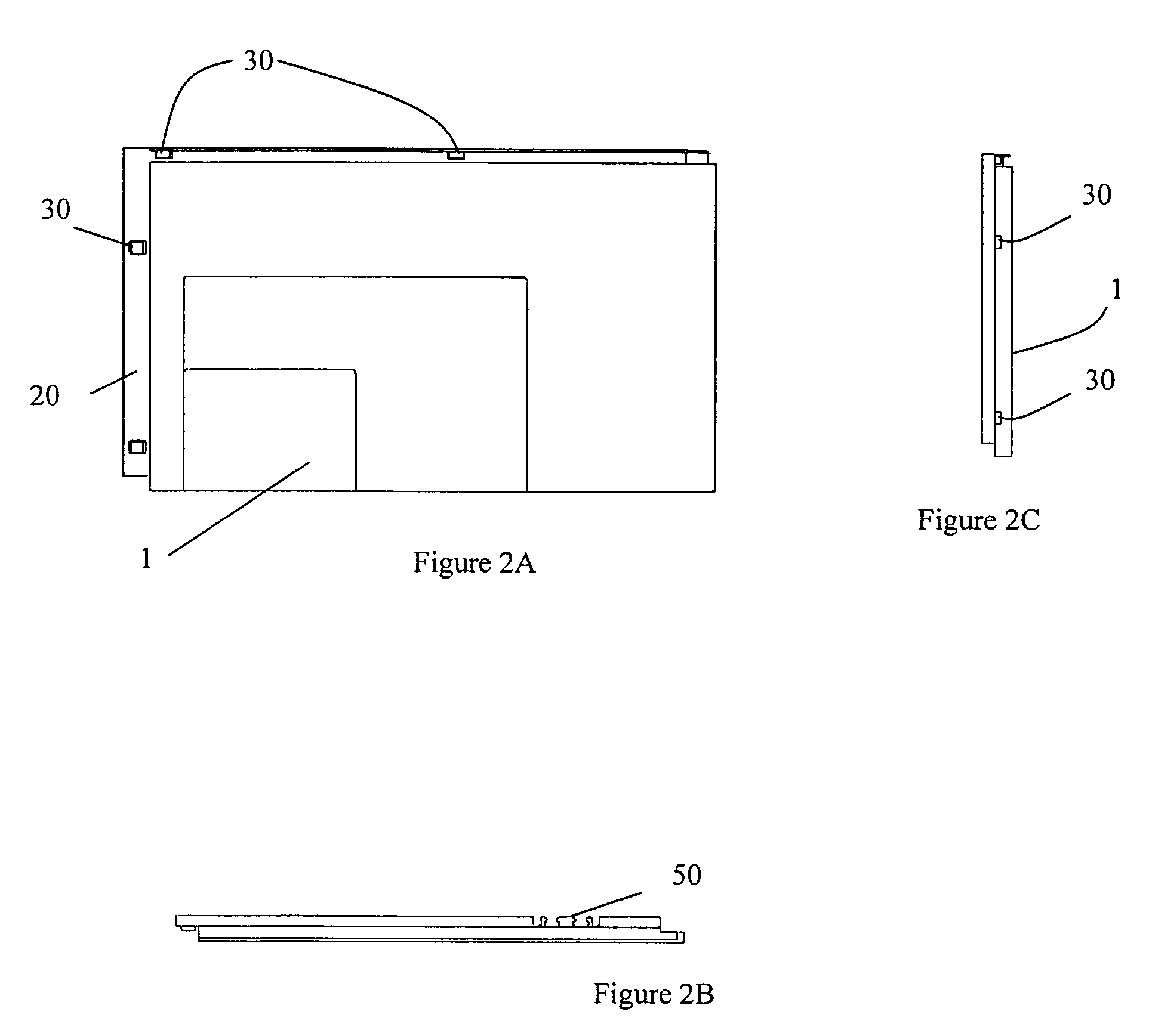
[0028]FIG. 2A shows the tile (1). The features of the tile include a ledge (20) with bosses (30) that allow for overlap mating of adj...


PUM


Abstract

The invention provides a modular system that includes a composite tile, with or without integrated photovoltaic cells, a track system for assembly of the tiles to a structure, and a wiring system for the photovoltaic tile. The track and tiles are made of composite material. Molding and extrusion processes can be used for the manufacturing of the tile and track, including the integration of photovoltaic cells. The track lengths are fastened to the structure. The track and tile have mating features, such that the tile can be interlocked with the track. Adjacent tiles are installed with overlap. Photovoltaic cells can be molded into or assembled with the tile. A busbar or wire harness is assembled to the track. When the photovoltaic tile is interlocked with the track, the connectors of the photovoltaic cells engage the busbar or wiring harness to provide an electrical connection.

Description

[0001]This application claims priority from provisional patent application No. 60 / 758,185 filed on Jan. 12, 2006.BACKGROUND INFORMATION[0002]There are numerous methods available for affixing photovoltaic cells to residential and commercial roofing structures. The most common photovoltaic roofing product consists of a stand-alone solar panel, which mounts to an existing roof or structure, using frame supports or direct mounting to the structure. These products are used in addition to, and not in place of, existing roof structures. The wiring systems for these photovoltaic arrays use traditional parallel or series circuits, and standard crimp or lug type connections.[0003]In terms of standard roofing products, there are various examples of interlocking shingle type products made from a range of materials, including plastic, foam, and metals. These materials have been used in place of more traditional shingle material, such as baked clay, slate, cedar, and asphalt. While these alternat...

Claims


Application Information

Patent Timeline
Patent Type & Authority Patents(United States)
IPC IPC(8): E04D13/18F24S50/20
CPCE04D12/004F24J2/5211F24J2/5254F24J2/5256H02S20/25E04D2001/3447F24J2002/4665Y02B10/12Y02B10/20Y02E10/47F24J2002/0061F24S25/632F24S25/20F24S2025/6002F24S2020/13F24S2025/6004F24S25/634Y02E10/50Y02B10/10
Inventor METTEN, ERICH CHRISTIANRODDICK, TIMOTHY JAMESSCULTETY, JASON LEONARD
Owner SR CONSULTING
Learn More