
Magnetic sensor and manufacturing method therefor

a technology of magnetic sensors and manufacturing methods, applied in the field of magnetic sensors, can solve the problems of weak magnetic characteristics, deformation of protection films, and difficulty in precisely producing resistances based on magnetization directions of free layers, and achieve the effect of superior hysteresis characteristics

Active Publication Date: 2012-06-26
YAMAHA CORP
View PDF12 Cites 3 Cited by
  • Summary
  • Abstract
  • Description
  • Claims
  • Application Information

AI Technical Summary

Benefits of technology

The present invention provides a magnetic sensor with superior hysteresis characteristics. The sensor has a planar surface and a slope, and includes a substrate, a silicon oxide film, magnetoresistive elements, lead films, a CVD oxide film, and a non-magnetic film. The non-magnetic film is formed between the magnetoresistive elements and the CVD oxide film, and is patterned to cover the periphery of the free layer in connection with each magnetoresistive element. The non-magnetic film prevents the magnetoresistive elements from absorbing oxygen and being oxidized during the manufacturing process. The sensor can detect magnetism in two-axial directions and three-axial directions, and is reliable and efficient in detecting magnetic fields.

Problems solved by technology

This drawback also occurs in the formation of protection films for coating tunnel magnetoresistive elements by way of plasma CVD.
When materials for use in free layers of GMR bars including giant magnetoresistive elements are oxidized, free layers are degraded in weak magnetic characteristics; this makes it difficult to precisely produce resistances based on magnetization directions of free layers.
This also increases hysteresis loops of magnetism, thus degrading hysteresis characteristics of magnetic sensors.
This drawback occurs with respect to giant magnetoresistive elements formed on planar surfaces and slopes; in particular, it remarkably occurs with respect to giant magnetoresistive elements formed on slopes.

Method used


Image

  • Magnetic sensor and manufacturing method therefor
  • Magnetic sensor and manufacturing method therefor
  • Magnetic sensor and manufacturing method therefor

Examples


Embodiment Construction

[0082]The present invention will be described in further detail by way of examples with reference to the accompanying drawings.

1. Magnetic Sensor

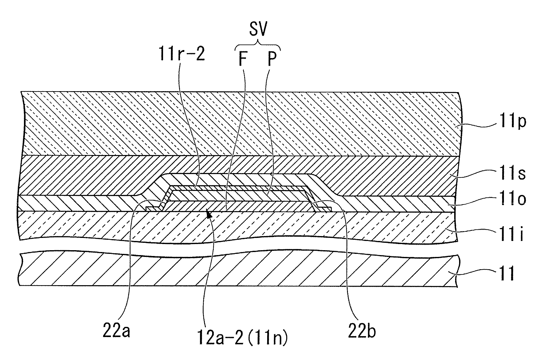
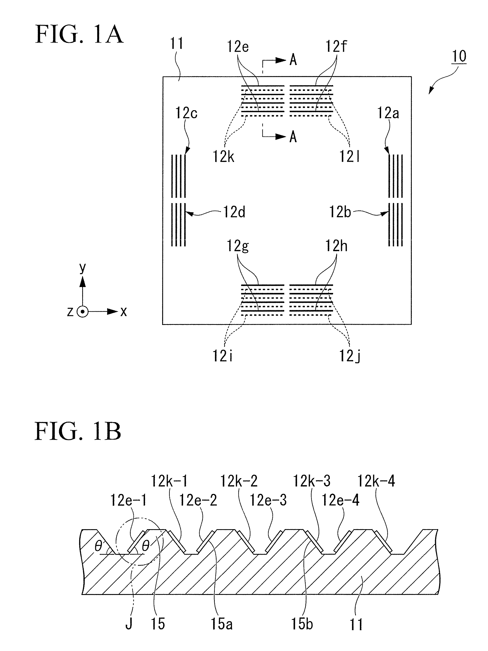
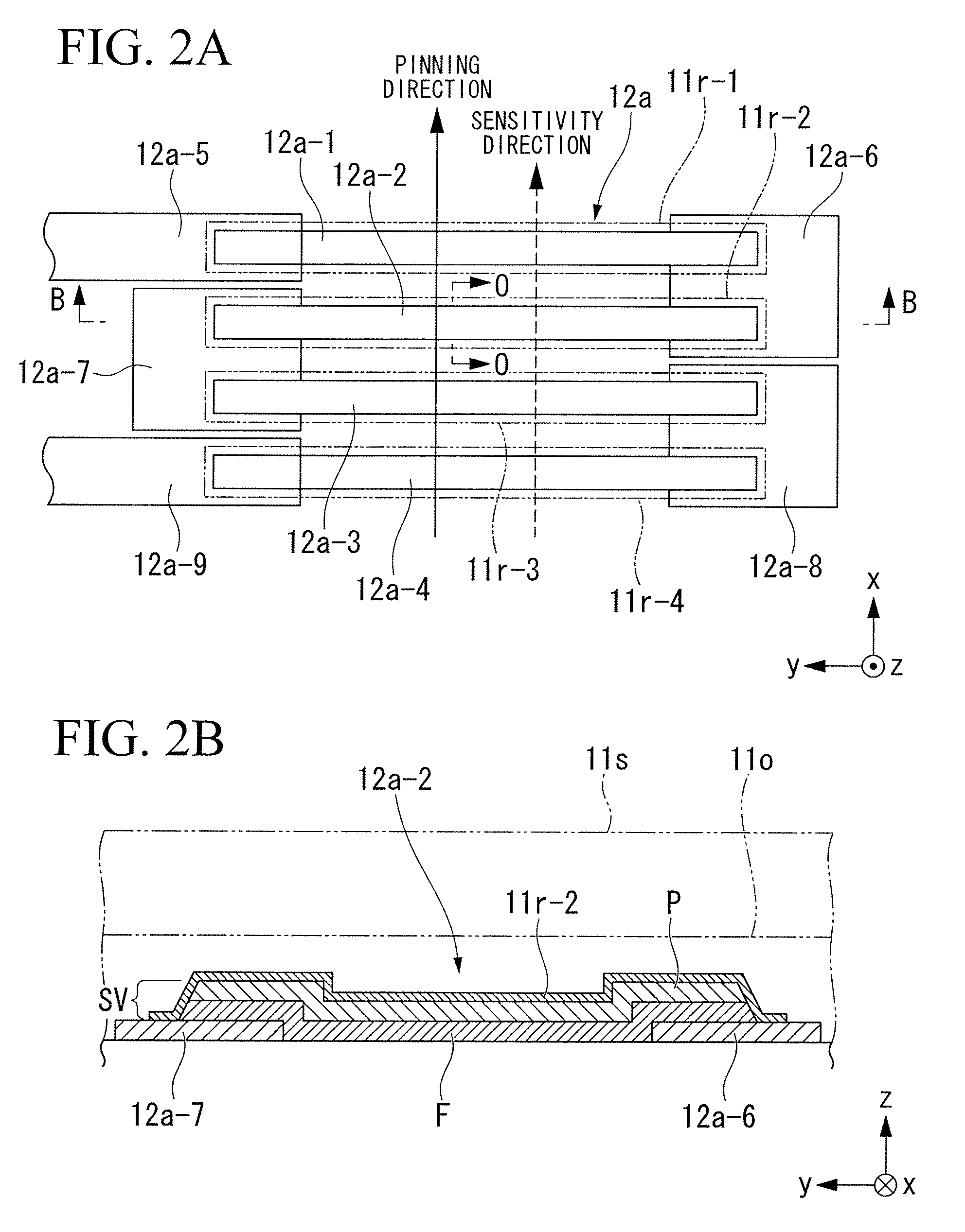
[0083]A three-axial magnetic sensor 10 according to a preferred embodiment of the present invention will be described with reference to FIGS. 1A, 1B, 2A, 2B, 3, 4A, 4B, 4C, 5, 6A, 6B, 7A, 7B, and 7C.

[0084]As shown in FIG. 1A, the three-axial magnetic sensor 10 is produced using a substrate 11 having a square shape in play view (defined by an X-axis and a Y-axis perpendicularly crossing each other) and a prescribed thickness (defined by a Z-axis perpendicular to the X-axis and Y-axis), wherein the substrate 11 is composed of quartz and silicon. In total, twelve GMR components each composed of four GMR bars (denoted by line segments and dotted line segments in FIG. 1A) are formed on the substrate 11. Specifically, there are provided X-axis GMR component 12a to 12d (see line segments drawn along the Y-axis), Y1-axis GMR components 12e to 12h (...


PUM


Abstract

A magnetic sensor for detecting magnetism in two-axial directions or three-axial directions is constituted of a substrate, a silicon oxide film that is formed on the substrate so as to form the planar surface and slopes, a plurality of magnetoresistive elements, each of which is formed by laminating a free layer, a conductive layer, and a pin layer on the substrate, a plurality of lead films that are formed to connect the magnetoresistive elements in series, a CVD oxide film for covering the magnetoresistive elements, and a non-magnetic film that is formed between the magnetoresistive elements and the CVD oxide film so as to cover the periphery of the free layer with respect to each magnetoresistive element. Thus, it is possible for the magnetic sensor to include the magnetoresistive elements having superior hysteresis characteristics.

Description

BACKGROUND OF THE INVENTION[0001]1. Field of the Invention[0002]The present invention relates to magnetic sensors, in which giant magnetoresistive elements are formed on a single substrate so as to detect intensities of magnetic fields in two-axial directions and three-axial directions. The present invention also relates to manufacturing methods of magnetic sensors.[0003]This application claims priority on Japanese Patent Application No. 2007-156378, the content of which is incorporated herein by reference.[0004]2. Description of the Related Art[0005]Conventionally, giant magnetoresistive elements (GMR elements) and tunnel magnetoresistive elements (TMR elements) have been know as elements for use in magnetic sensors. Each of these magnetoresistive elements includes a pin layer whose magnetization direction is fixed (or pinned) and a free layer whose magnetization direction varies in response to an external magnetic field, wherein it produces a resistance based on the relativity bet...

Claims


Application Information

Patent Timeline
Patent Type & Authority Patents(United States)
IPC IPC(8): H01L29/82H10N50/01H10N50/10
CPCB82Y25/00H01L29/82H01L27/22G01R33/093H10B61/00H10N59/00
Inventor AISO, KOKICHI
Owner YAMAHA CORP
Learn More