High torque active mechanism for orthotic and/or prosthetic devices

a high-torque active mechanism and orthotic technology, applied in non-surgical orthopedic devices, measurement devices, work measurement, etc., can solve the problems of not being able to use the joint does not help restore the natural dynamics of a healthy leg, and none of the commonly available orthotic knee joints can be used. , to achieve the effect of increasing the torque density during braking

Active Publication Date: 2012-07-03
NATIONAL BANK OF CANADA
View PDF84 Cites 27 Cited by
  • Summary
  • Abstract
  • Description
  • Claims
  • Application Information

AI Technical Summary

Benefits of technology

[0021]In accordance with yet another aspect of the present invention invention there is provided a joint actuator assembly for an orthotic and / or prosthetic joint, the joint actuator assembly comprising an MR damper to provide a controllable resistive torque on the axis of the orthotic and / or prosthetic joint and a friction brake mechanism in operational communication with the MR damper so as to be activated by the braking force generated by the MR damper thereby increasing torque density during braking.
[0022]In accordance with still yet another aspect of the invention, there is provided a knee joint actuator assembly for an orthotic and / or prosthetic knee joint, the knee joint actuator assembly comprising an MR damper to provide a controllable resistive torque on the axis of the orthotic and / or prosthetic knee joint and a friction brake mechanism in operational communication with the MR damper so as to be activated by the braking force generated by the MR damper thereby increasing torque density during braking.
[0023]In accordance with yet a further aspect of the present invention there is provided an orthotic joint comprising a joint actuator assembly comprising an MR damper to provide a controllable resistive torque on the axis of the orthotic joint and a friction brake mechanism in operational communication with the MR damper so as to be activated by the braking force generated by the MR damper thereby increasing torque density during braking.
[0024]In accordance with yet still another aspect of the present invention there is provided an orthotic knee joint comprising a knee joint actuator assembly comprising an MR damper to provide a controllable resistive torque on the axis of the orthotic knee joint and a friction brake mechanism in operational communication with the MR damper so as to be activated by the braking force generated by the MR damper thereby increasing torque density during braking.
[0025]In accordance with yet still a further aspect of the present invention there is provided a prosthetic joint comprising a joint actuator assembly comprising an MR damper to provide a controllable resistive torque on the axis of the prosthetic joint and a friction brake mechanism in operational communication with the MR damper so as to be activated by the braking force generated by the MR damper thereby increasing torque density during braking.
[0026]In accordance with still another aspect of the present invention there is provided an prosthetic knee joint comprising a knee joint actuator assembly comprising an MR damper to provide a controllable resistive torque on the axis of the prosthetic knee joint and a friction brake mechanism in operational communication with the MR damper so as to be activated by the braking force generated by the MR damper thereby increasing torque density during braking.

Problems solved by technology

This type of joint does not help restore the natural dynamics of a healthy leg.
However, because the transitions between the locked and unlocked states are not smoothly controlled, the natural dynamics of a healthy leg is not restored.
None of the commonly available orthosis knee joints on the market, and only a few prosthetic knees, allow the users to descend inclines and stairs because of the absence of controlled flexion during the stance phase.
For example, an electric motor and gear set incorporated in an actuated hinge could provide the required torque and motion control, but is likely to be noisy, heavy and bulky.
However, these systems are difficult to package on orthotic devices due to the size of the components and to the mechanical arrangement of those parts on the leg support system.
However, the motor requires a transmission system in order to provide the required torque and incorporating a transmission to the control system adds design complexity, weight and size to the solution.
The magnetorheological (MR) Damper technology utilized in the Rheo Knee™ from Ossur demonstrates excellent controllability and provides a good torque density, although not sufficient for an orthotic application.

Method used


Image

  • High torque active mechanism for orthotic and/or prosthetic devices
  • High torque active mechanism for orthotic and/or prosthetic devices
  • High torque active mechanism for orthotic and/or prosthetic devices

Examples


Embodiment Construction

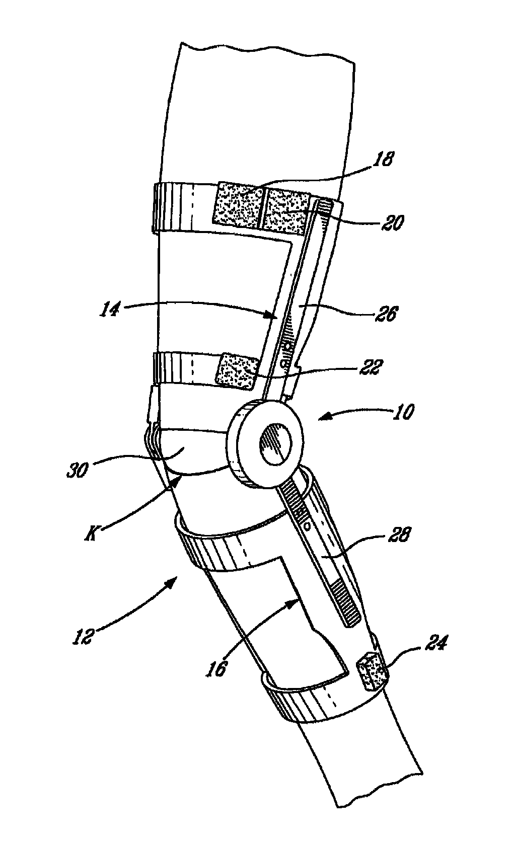
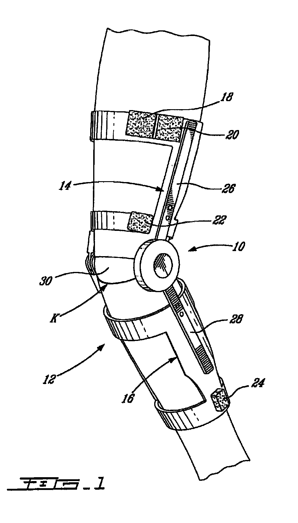
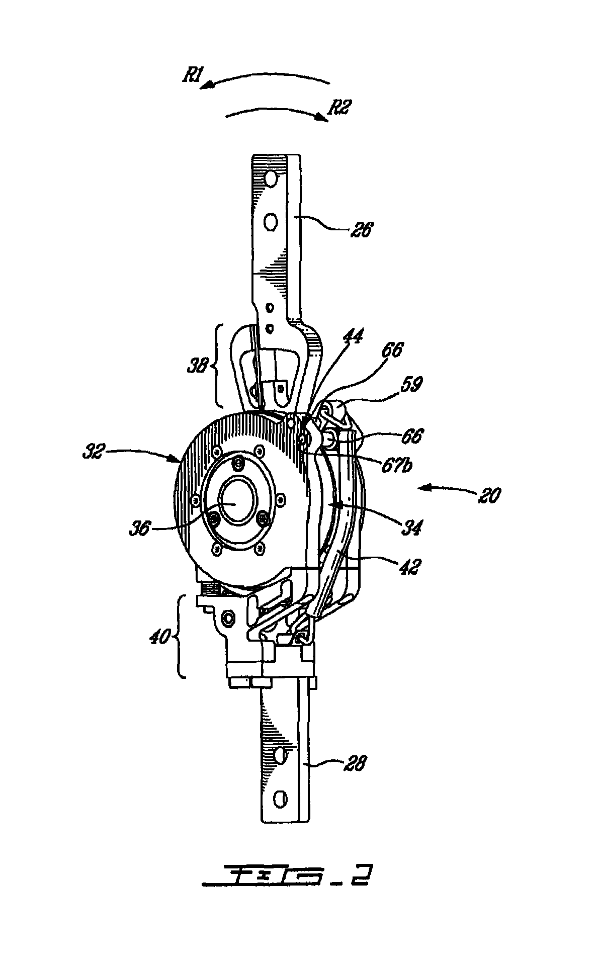
[0040]Generally stated, the present invention provides an orthotic / prosthetic device comprising at least one device portion (an orthotic portion or a prosthetic portion), a joint portion for providing for the at least one device portion to pivot between flexion and extension movements relative to another adjacent device portion or an adjacent limb segment of the user. A primary brake is in operational communication with the joint portion for generating a braking force thereon during flexion and / or extension movements. An additional frictional brake is in operational communication with both the primary brake and the joint portion. During flexion the primary brake causes the additional frictional brake to generate an additional frictional braking force on the joint portion.

[0041]Generally stated, a non-limitative illustrative embodiment of the present invention provides high torque active mechanism for an orthotic and / or prosthetic joint using a magnetorheological (MR) rotational damp...


PUM


Abstract

A high torque active mechanism for an orthotic and / or prosthetic joint using a primary brake which can be provide by magnetorheological (MR) rotational damper incorporating and an additional friction brake mechanism driven by the braking force generated by the MR damper. This combination of MR damper and friction brake mechanism allows an increase in torque density while keeping the same level of motion control offered by the MR damper alone. The increased torque density achieved by this high torque active mechanism allows to minimize the size of the actuating system, i.e. its diameter and / or breath, while maximizing its braking torque capability. In this regard, the friction brake mechanism is advantageously positioned around the MR damper, such that the dimension of the package is minimized.

Description

FIELD OF THE INVENTION[0001]The present invention relates to a joint actuation mechanism for orthotic and / or prosthetic devices. More particularly but not exclusive, the present invention relates to high torque active mechanism for orthotic and / or prosthetic devices.BACKGROUND OF THE INVENTION[0002]Many types of knee joints for orthotic and prosthetic devices are commonly available on the market. The most rudimentary joints do not allow knee flexion during active tasks such as walking and can be manually unlocked for tasks such as sitting. This type of joint does not help restore the natural dynamics of a healthy leg.[0003]More advanced joints use mechanical design or electronic control allowing to automatically, albeit abruptly, switch between a locked state and an unlocked state of the knee hinge. This offers stability during the stance phase and flexion during the swing phase. However, because the transitions between the locked and unlocked states are not smoothly controlled, the...

Claims


Application Information

Patent Timeline
Patent Type & Authority Patents(United States)
IPC IPC(8): A61F5/00A61F2/64
CPCA61F2/64G01L3/1457A61F5/0125A61F5/013A61F2/68A61F2002/5004A61F2002/507A61F2002/5072A61F2002/6818A61F2002/6854A61F2002/701A61F2002/741A61F2002/745A61F2002/747A61F2002/7635A61F2002/7645A61F2005/0169A61F2005/0179A61F2/70A61F5/0102A61F2/74A61F2/741A61F2005/0155A61F2005/0167A61F2005/0188
Inventor GILBERT, BENOITLANDRY, DAVID
Owner NATIONAL BANK OF CANADA
Why Eureka
Try Eureka