
Conduction angle control of brushless motor
a brushless dc motor and conduction angle technology, which is applied in the direction of motor/generator/converter stopper, dynamo-electric converter control, pulse technique, etc., can solve the problems of low voltage between the respective terminals of the brushless dc motor and narrow the working range of the inverter, so as to reduce the conduction angle and improve the responsiveness to changes. , the effect of enlarging the position sensible period
- Summary
- Abstract
- Description
- Claims
- Application Information
AI Technical Summary
Benefits of technology
Problems solved by technology
Method used
Image

Examples
Embodiment Construction
[0064]An exemplary embodiment of the present invention is demonstrated hereinafter with reference to the accompanying drawings. Not to mention, this embodiment does not limit the present invention.
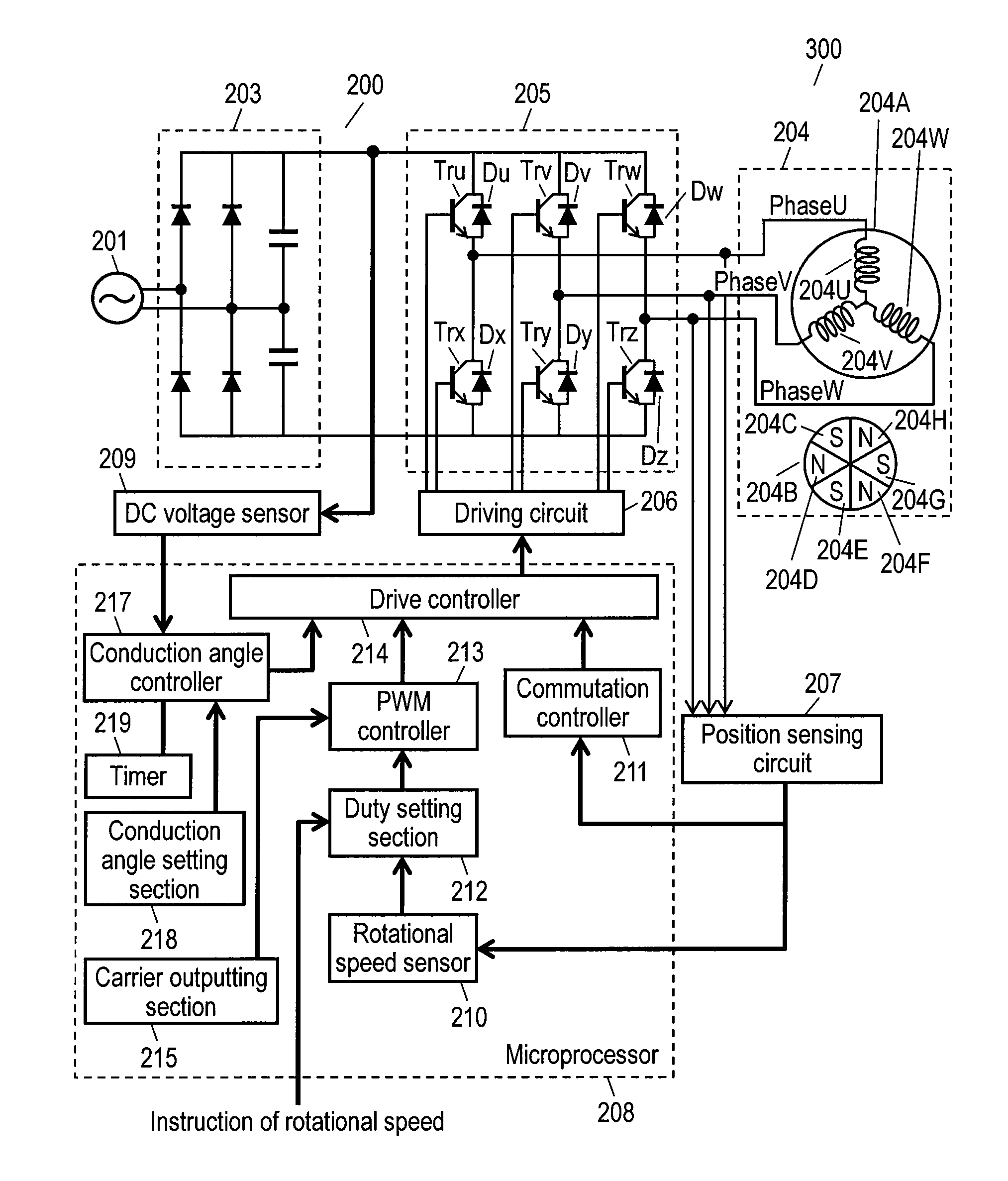
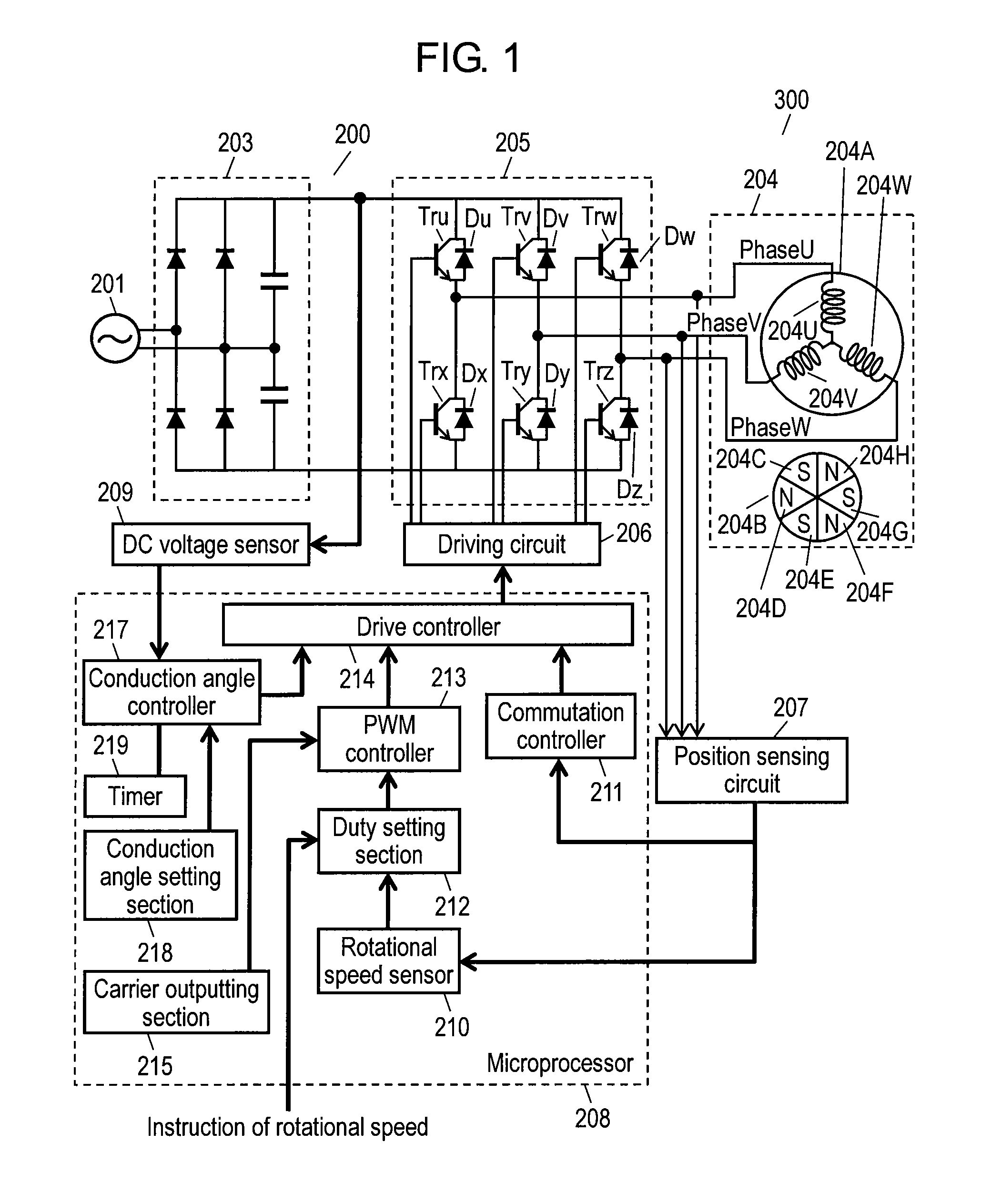
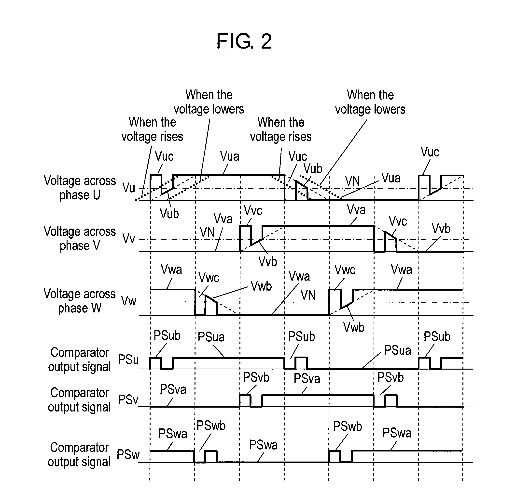
[0065]FIG. 1 shows a structure of an inverter controller in accordance with this embodiment of the present invention. FIG. 2 is a timing chart showing waveforms of respective sections in the inverter controller and timing the processes done by the respective sections. FIG. 3 shows characteristics indicating the relation between conduction angles and voltage variations in a power supply of the inverter controller. FIG. 4 is a timing chart showing operation of the inverter controller when a voltage changes in the inverter controller.
[0066]As shown in FIG. 1, inverter controller 200 is coupled to commercial AC power supply 201 and brushless DC motor (hereinafter simply referred to as “motor”) 204, and drives motor 204. Inverter controller 200 and motor 204 thus form motor driving device 300. ...
PUM
 Abstract
Description
Claims
Application Information