Wheel support bearing assembly

a technology for supporting bearings and bearing assemblies, which is applied in the direction of bearing units, rigid supports, transportation and packaging, etc., can solve the problems of low energy that can be absorbed, low toughness, and unexpected load on the supporting bearing assembly, and achieve excellent toughness and increase the load leading to impairment against impact load

Inactive Publication Date: 2012-07-10
NTN CORP
View PDF14 Cites 6 Cited by
  • Summary
  • Abstract
  • Description
  • Claims
  • Application Information

AI Technical Summary

Benefits of technology

[0021]Therefore, an object of the present invention is to provide a wheel support bearing assembly in which the outer member has an excellent toughness and in which the load leading to impairment against the impact load can be increased.
[0023]When the outer member serving as the stationary member is thermally refined by means of the quenching treatment and the high temperature tempering process, the toughness of the outer member, particularly that exhibited at a low temperature, can be increased. As a result, the resistance characteristic to the impact load can be increased. Namely, the load leading to impairment against the impact load can be increased. In this way, in the event that the automotive vehicle skids and lateral side or vehicle wheels thereof shockingly collide sidewise against the curbside, even though the impact load is loaded on the wheel support bearing assembly, failure of the automotive vehicle to run with the wheel support bearing assembly in its entirety separated from the automotive body structure and the possibility of the vehicle wheel separated and then rolling to collide against an external object can be avoided. Also, since a layer of 2 mm depth from the surface of the outer member represents the micro-pearlite structure, even with the carbon steel having a poor hardenability the toughness of the outer member can be increased due to the presence of the micro-pearlite structure that is excellent in toughness of the surface.
[0024]In the present invention, the outer member may have the outer periphery provided with a vehicle body fitting flange, which has female screw holes defined therein for bolting from an inboard side to the vehicle body structure. Even where those female screw holes are provided, the thermal refinement of the outer member is effective to provide an excellent resistance characteristic to the impact load.
[0025]In the present invention, the outer member may have the outer periphery provided with a vehicle body fitting flange, which has bolt insertion holes defined therein for bolting from an outboard to the vehicle body structure and a turned surface or a countersunken surface which defines a seat surface of a vehicle body fastening bolt. Even where those bolt insertion holes and seat surfaces turned or countersunken are provided, the thermal refinement of the outer member is effective to provide an excellent resistance characteristic to the impact load.

Problems solved by technology

When the road surface is ice covered, the atmospheric temperature is low, and when the automotive vehicle then parked in the open air skids to collide against the curbside soon after the start of travel from the parked condition, the load is unexpectedly imposed on the wheel support bearing assembly while the latter is in a cold condition.
In the case of the brittle fracture, the energy that can be absorbed is low and the toughness is low.
Where the fracture transition temperature is high, it turns out that the material is low in toughness even at high temperature.
On the other hand, if the fracture transition temperature is low, it turns out that the material is high in toughness even at low temperature.
From the above described results of the Charpy impact test, it has been certain that when the impact load acts on the above described wheel support bearing assembly while the latter is in the cold condition, the outer member of the structure as forged is susceptible to the chilled load while the toughness is lowered at the low temperature and, therefore, there is the possibility that the vehicle body fitting flange, which has been made compact and lightweight, will be fractured to such an extent that the wheel support bearing assembly itself may depart from the automotive vehicle.

Method used


Image

  • Wheel support bearing assembly
  • Wheel support bearing assembly
  • Wheel support bearing assembly

Examples


Embodiment Construction

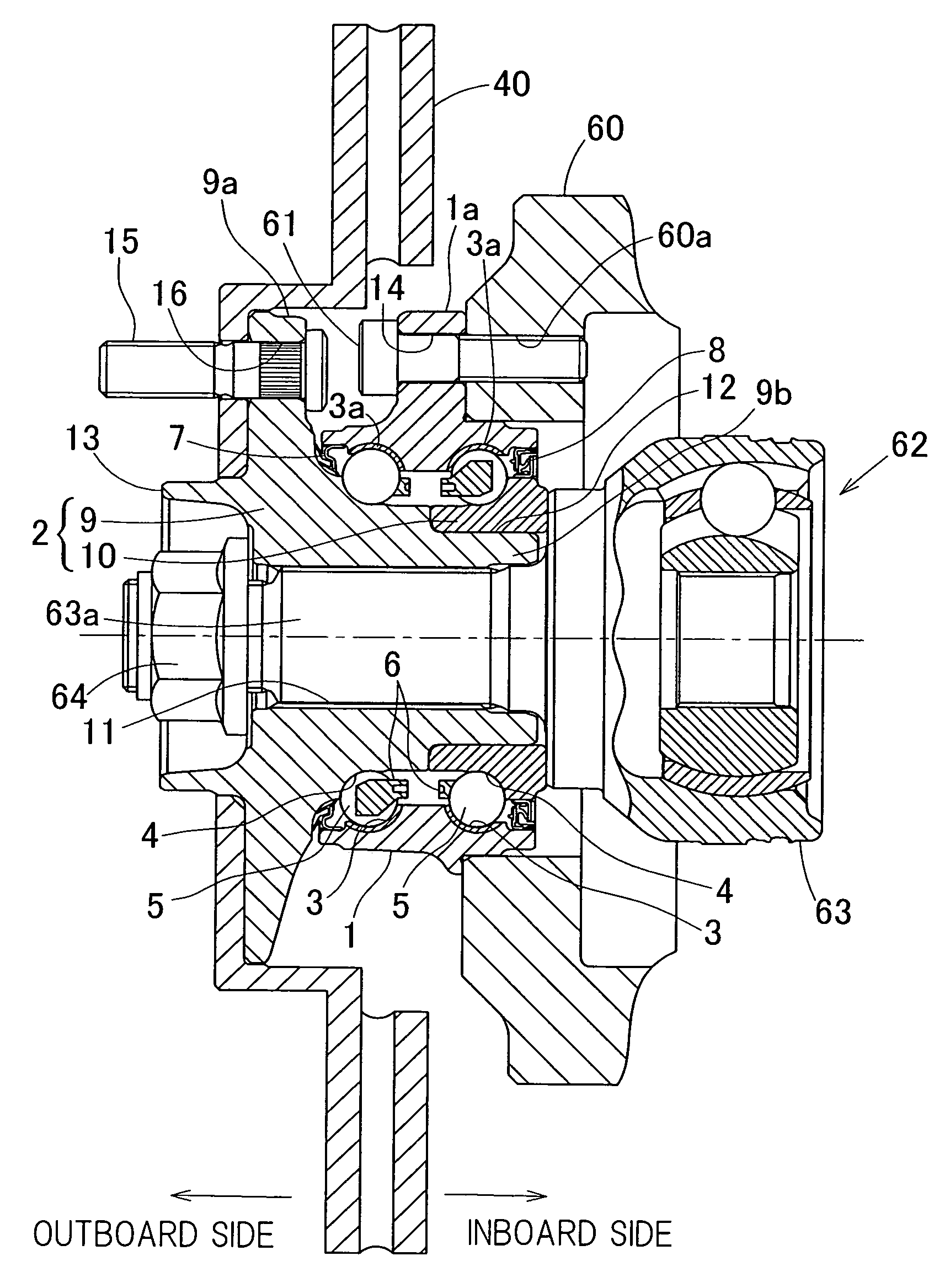
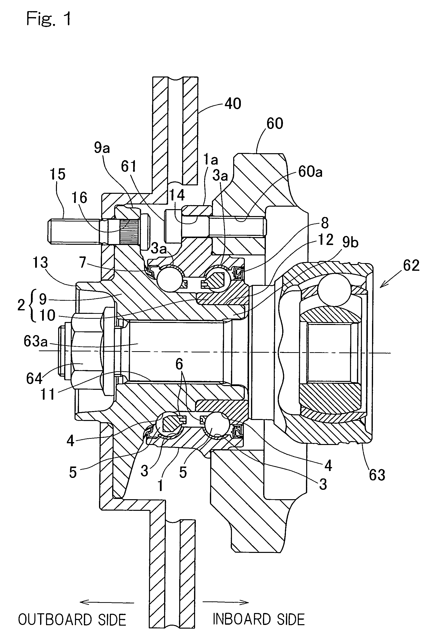
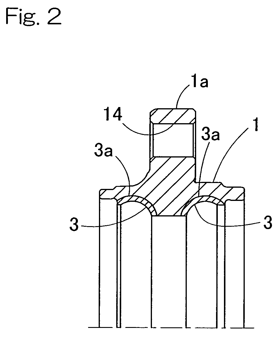
[0044]A first preferred embodiment of the present invention will be described in detail with particular reference to FIGS. 1 and 2. The wheel support bearing assembly according to this embodiment is a double row angular contact bearing model for use in an automotive vehicle, which is classified as a third generation type, and is an inner ring rotating type for supporting a vehicle drive wheel. It is to be noted that hereinafter in this specification, terms “outboard” and “inboard” represent one side of the vehicle body away from the longitudinal center of the vehicle body and the other side of the vehicle body close to the longitudinal center of the vehicle body, respectively, when assembled in the vehicle body.

[0045]This wheel support bearing assembly includes, as best shown in FIG. 1 in a sectional representation, an outer member 1 having an inner periphery formed with a plurality of rows of raceway surfaces 3, an inner member 2 having an outer periphery formed with raceway surfac...


PUM


Abstract

A wheel support bearing assembly includes an outer member (1), which serves as a stationary member and has an inner periphery formed with a plurality of rows of raceway surfaces (3), an inner member (2), which serves as a rotatable member and has an outer periphery formed with respective raceway surfaces (4) opposed to the previously described raceway surfaces (3), and a plurality of rows of rolling elements (5) interposed between the respective opposed raceway surfaces (3, 4). The outer member (1) is thermally refined by means of a quenching and a high temperature tempering process so that a layer of at least 2 mm in depth from a surface of the outer member is rendered to have a micro-pearlite structure.

Description

CROSS REFERENCE TO THE RELATED APPLICATIONS[0001]This application claims the benefit under 35 U.S.C. Section 371 of PCT International Application No. PCT / JP2009 / 000457, filed Feb. 6, 2009, which claimed priority to Japanese patent application No. 2008-031847, filed Feb. 13, 2008, the entire disclosures of which are herein incorporated by reference as a part of this application.FIELD OF THE INVENTION[0002]The present invention relates to a wheel support bearing assembly for use in automotive vehicles and freight cars, which is designed to have a high strength.BACKGROUND ART[0003]In the conventional wheel support bearing assemblies of the second and third generation types, in which the inner member is utilized as a rotatable member and the outer member as a stationary member, the outer member is generally formed with a vehicle body fitting flange on an outer periphery thereof and, therefore, the use is made of a medium carbon steel such as, for example, S53C as a material for the oute...

Claims


Application Information

Patent Timeline
Patent Type & Authority Patents(United States)
IPC IPC(8): F16C13/00
CPCB60B27/0005B60B27/001B60B27/0042B60B27/0084B60B27/0094F16C19/186F16C33/64F16C19/386F16C19/184F16C2204/64Y10S384/913F16C2326/02F16C19/185F16C19/187
Inventor HIRAI, ISAO
Owner NTN CORP
Why Eureka
Try Eureka