
Fuel cell power generation system

a fuel cell and power generation technology, applied in the direction of fuel cells, emergency supply, sustainable buildings, etc., can solve the problems of difficult time-consuming and laborious cleaning of fuel or electrolyte spills, high cost of transporting such equipment and fuel, and limited implementation of fuel cell systems in real-world applications. achieve the effect of reducing stack stress

Inactive Publication Date: 2012-07-10
BRITISH COLUMBIA HYDRO & POWER AUTHORITY
View PDF7 Cites 7 Cited by
  • Summary
  • Abstract
  • Description
  • Claims
  • Application Information

AI Technical Summary

Benefits of technology

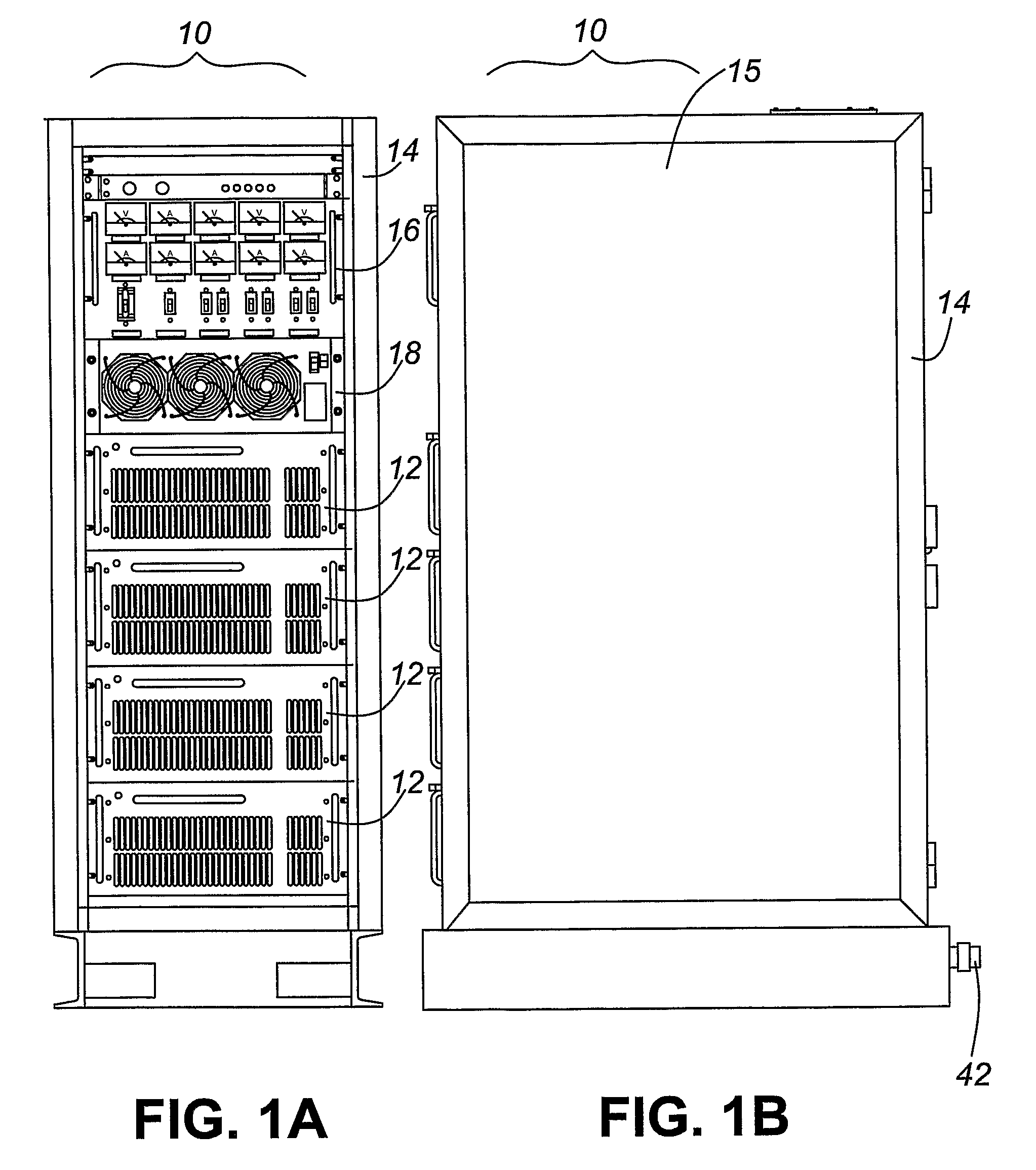
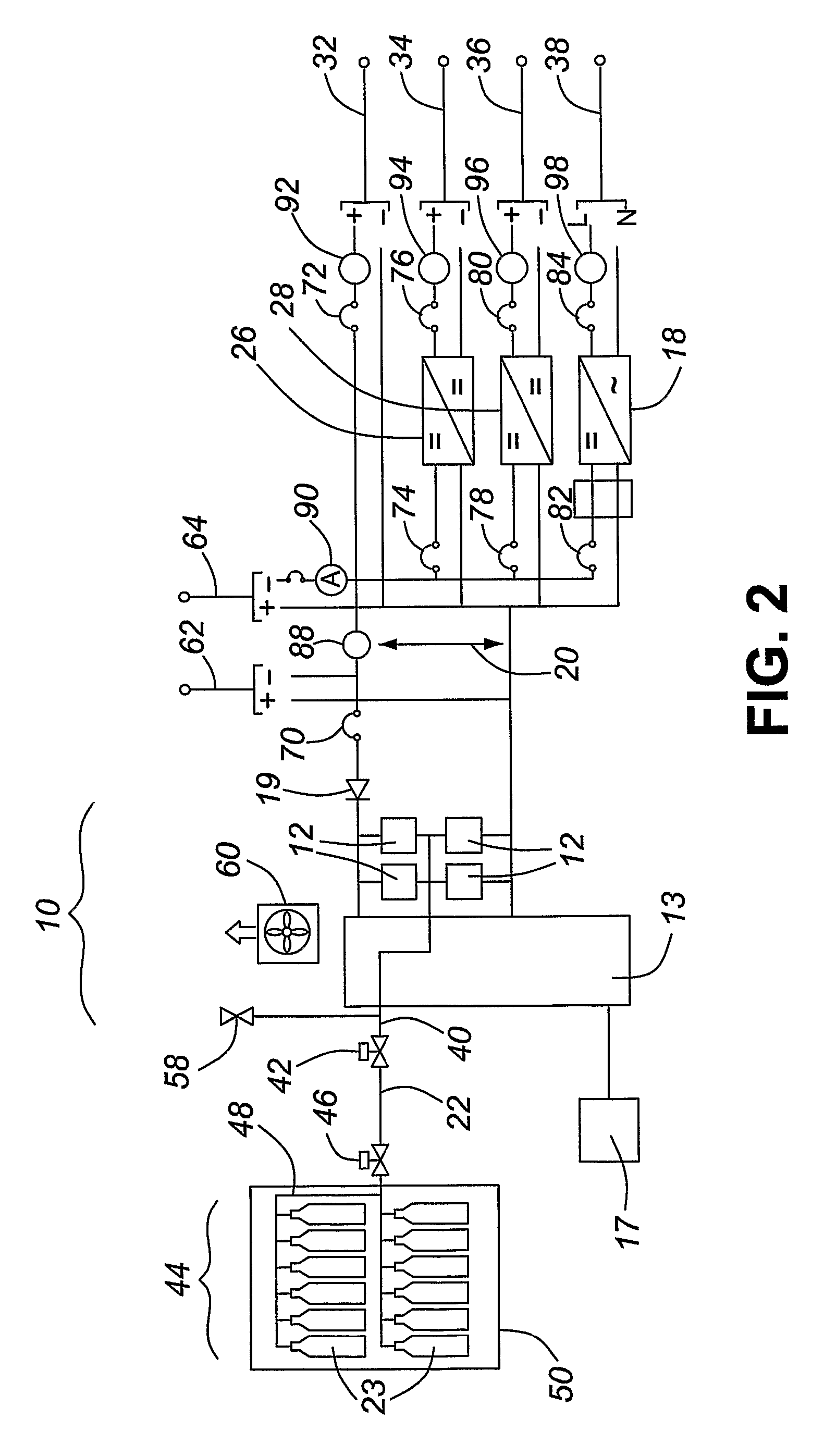
[0011]According to one aspect of the invention, there is provided an electric power generator that is particularly suitable for providing back-up power to sites with multiple power requirements. This generator comprises: a rack having multiple module bays; at least one fuel cell stack mounted in one of the bays; and at least one power conversion module mounted in one of the bays. The power conversion module is electrically coupled to the fuel cell stack and converts the voltage level and / or current type of some of the electricity produced by the stack such that the generator can simultaneously output electricity at multiple voltage levels and / or current types. The rack can be a standardized nineteen relay rack, making the generator relatively compact and compatible with sites configured accept such racks.
[0015]The generator can have a design load and at least one more fuel cell stack than is required to meet the design load. In such case, the generator would further comprise means for electrically decoupling at least one fuel cell stack from the generator and switching an operating load to the remaining coupled fuel cell stack or stacks. The operating load can be shared between all the fuel cell stacks to reduce stress on the stacks. When one of the stacks fail, the generator can switch the operating load to the remaining functioning stacks until the failed stack can be replaced. Alternatively, the operating load can be shared between the minimum number of fuel cell stack(s) required to meet the design load, with the remaining fuel cell stack(s) electrically decoupled from the generator and maintained in standby mode. When one of the operating stacks fail, the generator can activate the stack(s) in standby mode.

Problems solved by technology

Such remote stations present an environmental concern, as the large stores of diesel fuel and battery electrolyte pose a significant environmental hazard.
As these locations are hard to reach, timely clean up of fuel or electrolyte spills are particularly difficult.
Furthermore, such back up power source should be relatively light and compact: existing back up equipment comprising diesel generators, diesel fuel storage, and batteries tend to be relatively heavy; as access to remote stations can often only be made by helicopter, transporting such equipment and fuel tends to be expensive.
Failures of lead-acid battery based back up systems to operate properly during blackouts have prompted utilities to examine alternative sources for back-up power.
However, actual implementation of such fuel cell systems in real world applications have been very limited, as there are significant technological hurdles to overcome to ensure the fuel cell systems can effectively and reliably operate in the field.
One particular challenge is to provide a cost-effective and compact fuel cell system that can be readily adapted to provide power at a site having multiple electrical devices with different voltage and current requirements.

Method used


Image

  • Fuel cell power generation system
  • Fuel cell power generation system
  • Fuel cell power generation system

Examples


first embodiment

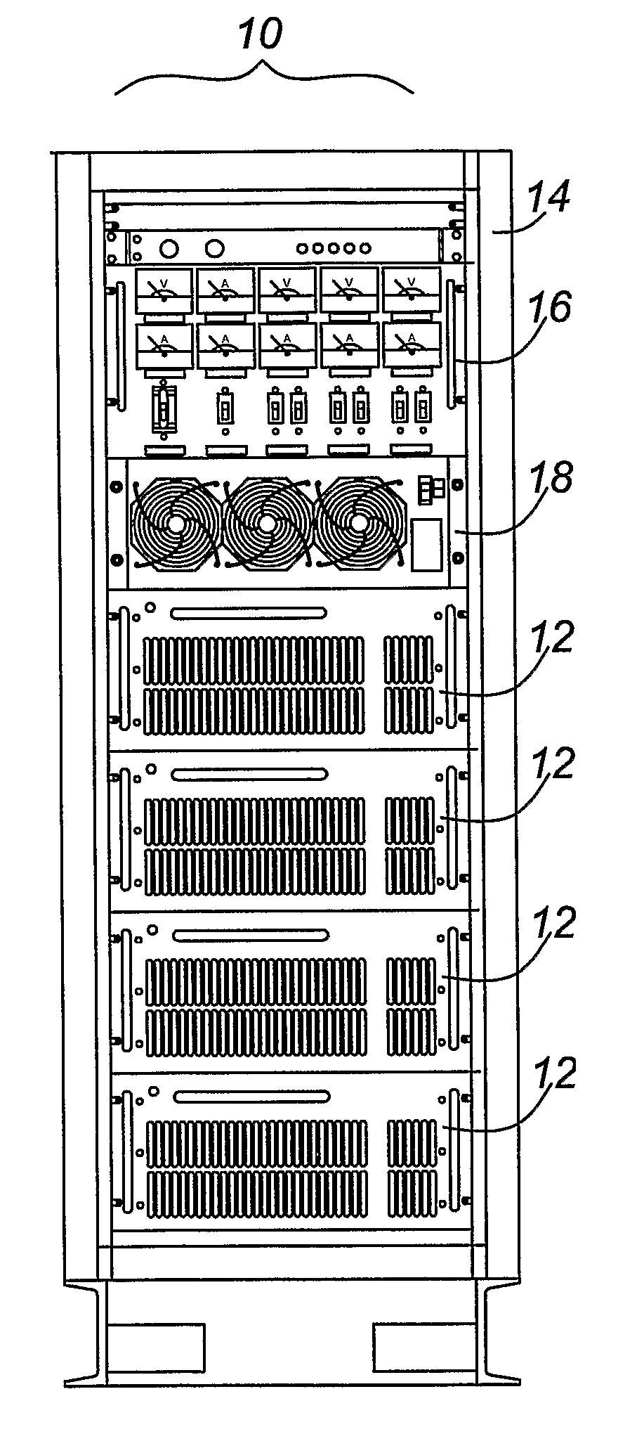
[0025]FIGS. 1-4 relate to the invention. The system 10 shown in FIGS. 1(a) and (b) has a standardized relay rack 14, or “nineteen inch rack” as popularly referred to in the telecommunications and computing industries. The rack 14 is a standardized (EIA 310-D, IEC 60297 DIN 41494 SC48D) system for mounting various modules in the rack 14. The rack 14 consists of two long, thin metal plates 15 standing vertically in the same plane with a space of approximately eighteen inches between them. Sliders (not shown) are mounted to each plate 15 at vertical intervals to define bays to receive components within the rack 14. It is within the scope of the invention to modify the rack height to provide more or fewer component bays.

[0026]The system 10 comprises multiple components that are configured to mount within the rack 14; in particular, the components each have a width and depth that correspond to the rack's width and depth, and a height that is a multiple of a standard unit of rack height, ...

second embodiment

[0057]According to the invention, and referring to FIG. 5(a), the metering and power conversion module 16 is replaced by a metering module 110, and all power conversion is performed by separate power conversion modules 18 that can be mounted in the rack 14 and electrically connectable together and to electrically powered devices via an output bus assembly 112. Furthermore, rack control and hydrogen supply control are combined with monitoring, annunciation and communications control into a single control module 113 mounted on the rack 14. By modularizing all of the power conversion components, this system 10 can be easily configured to meet the specific power needs of a particular site. The output bus assembly 112 enables the power conversion components to be easily swapped, therefore enabling the system 10 to be easily reconfigured to meet different power needs.

[0058]The metering module 110 is similar to the metering and power conversion module 16 except that it does not contain any...


PUM

PropertyMeasurementUnit
poweraaaaaaaaaa
currentaaaaaaaaaa
AC voltageaaaaaaaaaa

Abstract

An electric power generator is particularly suitable for providing back-up power to sites with multiple power requirements. This generator comprises a rack having multiple module bays; at least one power conversion module is mounted in one of the bays and is electrically coupled to a fuel cell stack also mounted in the rack or located remote from the rack. The power conversion module converts the voltage level and / or current type of some of the electricity produced by the stack such that the generator can simultaneously output electricity at multiple voltage levels and / or current types. The rack can be a standardized nineteen relay rack, making the generator relatively compact and compatible with sites configured accept such racks.

Description

BENEFIT CLAIMS[0001]This application is a US National Stage of International Application No. PCT / CA2005 / 001454, filed 23 Sep. 2005, which claims the benefit of CA 2,482,486, filed 24 Sep. 2004.FIELD OF THE INVENTION[0002]This invention relates generally to a system for generating electrical power using hydrogen fuel cells.BACKGROUND OF THE INVENTION[0003]Reliability of a customer's power supply is a primary concern for a utility. In order to provide reliable and continuous power, the utility tries to ensure that its equipment is always in working order. Utilities typically have generating stations, sub-stations, and telecommunications, system control and computer networks that should be operating at all times. To ensure continuous operation, many of these systems are provided with back-up power sources for providing temporary power whenever their main power sources are disrupted.[0004]For example, a utility may have a communications network that includes microwave repeater stations ...

Claims


Application Information

Patent Timeline
Patent Type & Authority Patents(United States)
IPC IPC(8): H01M8/04H01M8/24H01M2/02H01M8/02
CPCH01M8/02H01M8/04559H01M8/04589H01M8/04597H01M8/04626H01M8/04925H01M8/04955H01M8/2465H02J7/34H02J9/062H01M8/04664H01M8/04746H01M8/04753H01M2250/10H02J2001/004Y02B90/14Y02E60/50H02J2300/30Y02B90/10H01M8/2475H01M8/0297
Inventor LAM, ALEX
Owner BRITISH COLUMBIA HYDRO & POWER AUTHORITY
Learn More