
Wind turbine generator and blade pitch angle control method thereof

a technology of wind turbine generator and control method, which is applied in the direction of electric generator control, rotor, vessel construction, etc., can solve the problems of increasing the weight and cost of the wind turbine generator, excessive load generated in the entire wind turbine, and so as to reduce the maximum load and reduce the individual pitch angle without increasing the aerodynamic imbalance of the wind turbine rotor

Active Publication Date: 2012-07-10
MITSUBISHI HEAVY IND LTD
View PDF42 Cites 13 Cited by
  • Summary
  • Abstract
  • Description
  • Claims
  • Application Information

AI Technical Summary

Benefits of technology

[0028]According to the present invention, when shutdown is performed, it is possible to reduce an individual pitch angle without increasing an aerodynamic imbalance of a wind turbine rotor even after the shutdown is started. As a result, it is possible to further reduce the maximum load that becomes a design constraint of a wind turbine, and to realize a blade pitch angle control method of a light-weighted and inexpensive wind turbine generator.

Problems solved by technology

Therefore, an aerodynamic imbalance may be generated in the wind turbine rotor due to a difference in the blade pitch angles of the wind turbine blades.
Therefore, an excessive load generated in the entire wind turbine remains as a design constraint of the wind turbine due to the aerodynamic imbalance.
This excessive load is reflected in strength design of machine parts, thereby increasing weight and cost of the wind turbine generator.

Method used


Image

  • Wind turbine generator and blade pitch angle control method thereof
  • Wind turbine generator and blade pitch angle control method thereof
  • Wind turbine generator and blade pitch angle control method thereof

Examples


embodiment

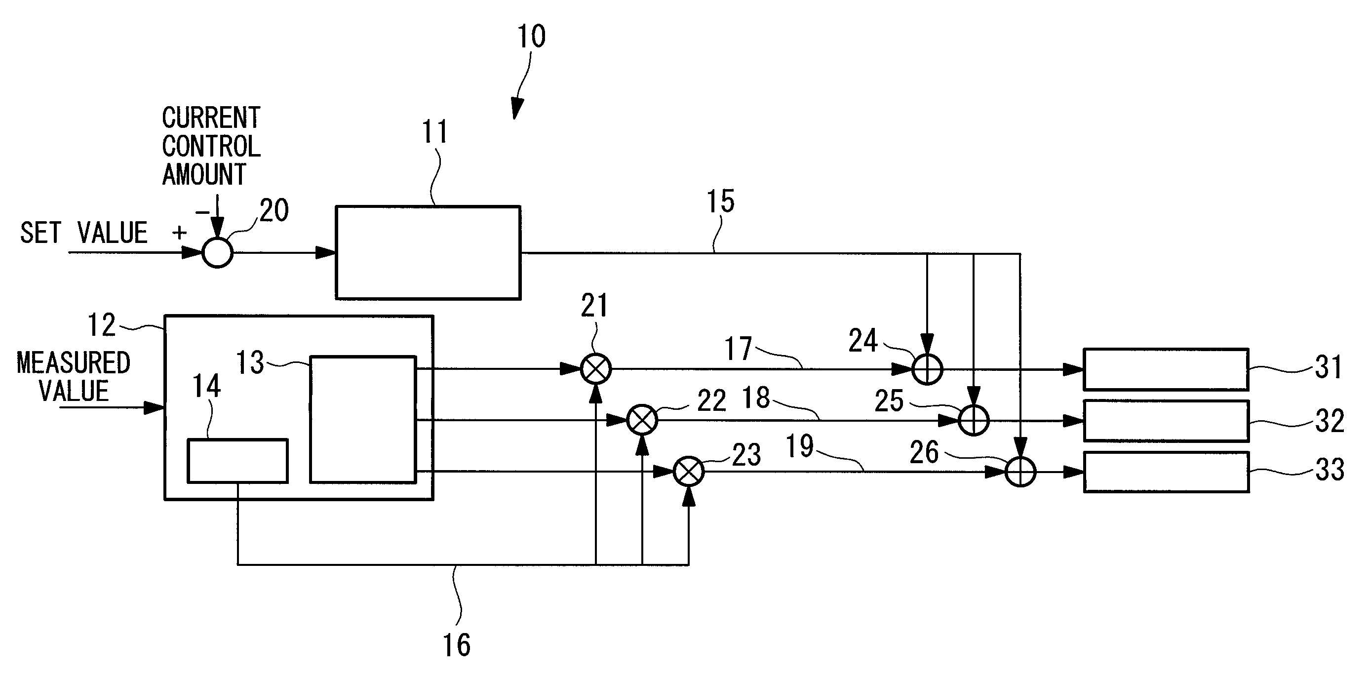
[0048]FIG. 1 is a block diagram showing a schematic structure of a blade pitch angle controller in the wind turbine generator according to an embodiment of the present invention.

[0049]In FIG. 1, a blade pitch angle controller 10 of the wind turbine generator of the present embodiment includes a collective pitch angle controller 11, an individual pitch angle controller 12, a subtractor 20, multipliers 21, 22 and 23, adders 24, 25 and 26, a first blade pitch actuator 31, a second blade pitch actuator 32 and a third blade pitch actuator 33.

[0050]The collective pitch angle controller 11 corresponds to a collective pitch angle producing means in claims, and produces a collective pitch angle demand that is common to blade pitch angles of the three wind turbine blades 1, 2 and 3. A deviation between the rotation speed, a set value of an output of generated electricity and a current control amount is obtained by the subtractor 20, and a collective pitch angle demand 15 is produced based on ...

first modification

[0075]In the above-described embodiment, when shutdown is performed, the individual pitch angle gain 16 is adjusted such that an individual pitch angle gain is reduced gradually and reaches to zero after the first set time by the individual pitch angle gain producing unit 14, and the reduction of the individual pitch angle gain 16 is started simultaneously when the shutdown is started. Alternatively, a predetermined individual pitch angle gain before the shutdown may be maintained during second set time (second set time is shorter than the first set time) after the shutdown is started, and adjustment may be performed such that the individual pitch angle gain is gradually reduced during a period from the second set time to the first set time.

[0076]FIG. 16 shows time transition G1 of the individual pitch angle gain 16 of the present modification. According to G1 in FIG. 16, second set time T1 is 4 seconds and first set time is 12 seconds. The individual pitch angle gain 16 is graduall...

second modification

[0081]In the above-described embodiment and the first modification, when shutdown is performed, the individual pitch angle gain 16 is gradually reduced by the individual pitch angle gain producing unit 14 based on the primary decreasing function. Alternatively, the individual pitch angle gain may be adjusted based on an n-order decreasing function (e.g., a secondary decreasing function) or a combination of the decreasing functions.

[0082]FIG. 17 shows time transition G2 of the individual pitch angle gain 16 of the present modification. According to G2 in FIG. 17, the individual pitch angle gain 16 is gradually reduced from 1 to 0.5 based on an elliptic function, and from 0.5 to 0 based on an inverse function.

[0083]By making it possible to variably set the reduction rate of the individual pitch angle gain 16 with time, shutdown can be controlled while flexibly responding to various situations such as wind conditions, driving situations, a scale of the wind turbine generator, and types...


PUM


Abstract

The present invention provides a wind turbine generator and a blade pitch angle control method thereof in which an aerodynamic imbalance of a wind turbine rotor at the time of shutdown is further reduced, the maximum load of a wind turbine is further reduced, and the wind turbine generator can be reduced in weight and cost. The wind turbine generator includes a collective pitch angle controller 11 that produces a collective pitch angle demand that is common to blade pitch angles of wind turbine blades, an individual pitch angle producing unit 13 that produces an individual pitch angle demand inherent in each wind turbine blade, multipliers 21 to 23 that multiply the individual pitch angle demand by the individual pitch angle gain; an individual pitch angle gain producing unit 14, and adder 24 to 26 that add collective pitch angle demands to the output of the multipliers 21 to 23 and supply the same to pitch actuators 31 to 33 inherent in the wind turbine blades. When shutdown is performed, the individual pitch angle gain is adjusted such that an individual pitch angle gain is reduced gradually and reaches to zero by the individual pitch angle gain producing unit 14 after first set time.

Description

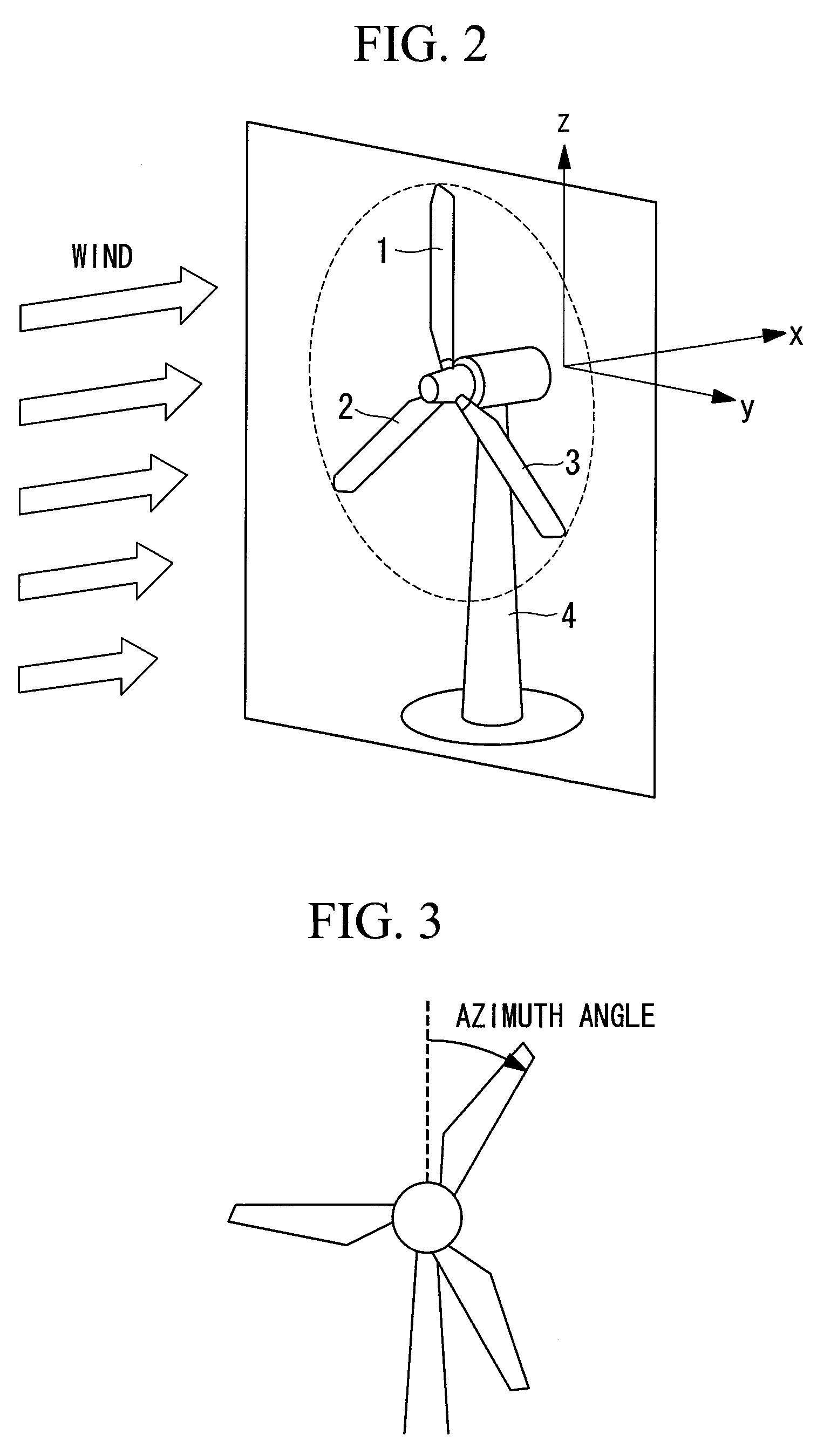
RELATED APPLICATIONS[0001]The present application claims the priority of International Application No. PCT / JP2010 / 051831 filed Feb. 8, 2010, the disclosure of which is hereby incorporated by reference herein in its entirety.TECHNICAL FIELD[0002]The present invention relates to an individual pitch angle control type wind turbine generator and a blade pitch angle control method thereof, and more particularly, to a wind turbine generator and a blade pitch angle control method thereof for further reducing an aerodynamic imbalance of a wind turbine rotor at the time of shutdown to further reduce the maximum load that becomes a design constraint of a wind turbine, and for reducing the wind turbine generator in weight and cost.BACKGROUND ART[0003]As shown in FIG. 2, a propeller type wind turbine used in a wind turbine generator includes a plurality of wind turbine blades (usually three wind turbine blades, and a structure having three wind turbine blades will be described herein). A blade ...

Claims


Application Information

Patent Timeline
Patent Type & Authority Patents(United States)
IPC IPC(8): F03D9/00H02P9/04
CPCF03D7/0224F03D7/024F03D7/0264F03D7/043Y02E10/723Y02E10/72
Inventor NAKASHIMA, TAKUMIBABA, MITSUYAHAYASHI, YOSHIYUKIIDE, KAZUNARI
Owner MITSUBISHI HEAVY IND LTD
Learn More