
Amplified radiation damping for MR imaging and spectroscopy

a technology of amplified radiation and imaging, applied in the field of amplified radiation damping for mr imaging and spectroscopy, can solve the problems of ssfp methods, intrinsic limitation of signal-to-noise ratio (snr) efficiency in mr experiments, and limiting longitudinal and transverse spin relaxation mechanisms

Inactive Publication Date: 2012-07-10
GENERAL ELECTRIC CO
View PDF1 Cites 5 Cited by
  • Summary
  • Abstract
  • Description
  • Claims
  • Application Information

AI Technical Summary

Benefits of technology

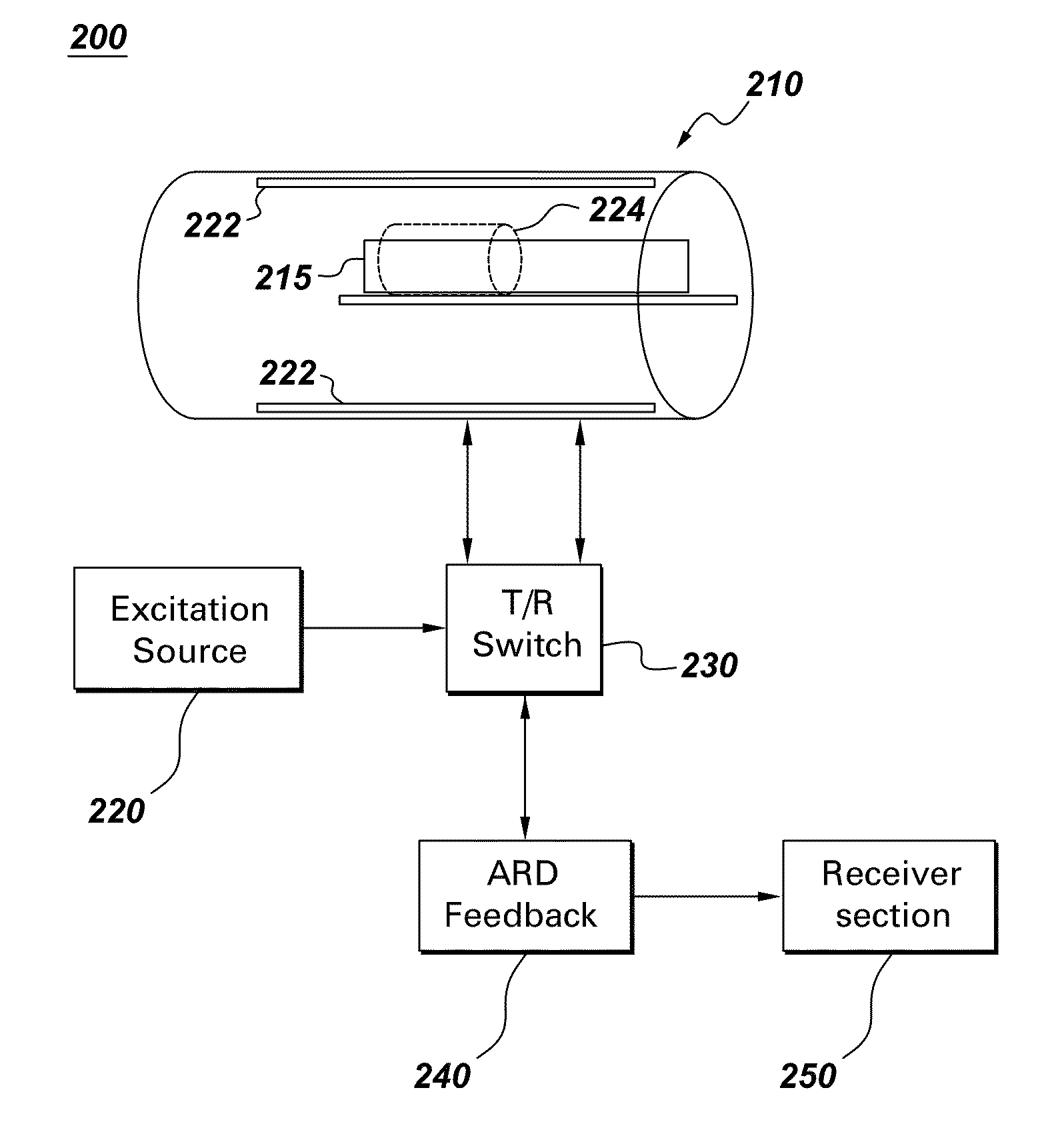
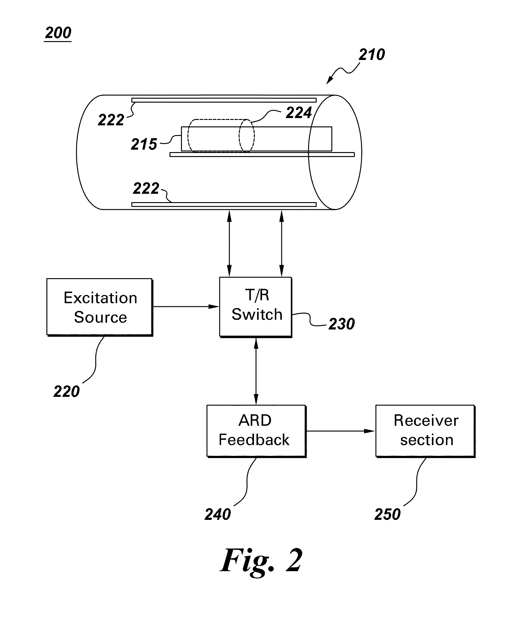
"The present patent relates to a system and method for improving medical imaging, such as magnetic resonance imaging and spectroscopy, by using amplified radiation damping (ARD). The system includes an imaging apparatus with coils and an excitation source for providing pulse sequences. A feedback section provides amplified radiation damping feedback to the imaging target to recover longitudinal magnetization after data acquisition. The feedback section has at least one amplifier and at least one attenuator to control the strength and phase of the amplified radiation damping feedback. The pulse sequences may include gradient-echo or spin-echo sequences, and the refocused signals are selectively processed and applied with amplified radiation damping feedback. The imaging method using amplified radiation damping provides improved image signals and generates images. The system and method have applications in magnetic resonance imaging and spectroscopy."

Problems solved by technology

The signal-to-noise ratio (SNR) efficiency in MR experiments is intrinsically limited by longitudinal and transverse spin relaxation mechanisms.
This becomes particularly limiting for short-repetition-time (TR) pulse sequences, where incomplete T1-relaxation results in a steady-state signal that is only a small fraction of the available thermal equilibrium magnetization.
Both fast recovery and SSFP methods are susceptible to various imperfections (i.e. off-resonance effects, flip-angle miss-calibration, transient effects, undesired refocusing echoes, etc.) and are therefore demanding in terms of robust implementation.
While there have been a variety of efforts to implement ARD feedback schemes, there continue to be unfavorable characteristics in the state of the art that remain unresolved.
In particular, previously presented ARD feedback schemes are generally limited in terms of flexibility and their ability to achieve adequate feedback gain.

Method used


Image

  • Amplified radiation damping for MR imaging and spectroscopy
  • Amplified radiation damping for MR imaging and spectroscopy
  • Amplified radiation damping for MR imaging and spectroscopy

Examples


Embodiment Construction

[0031]In the following detailed description, numerous specific details are set forth in order to provide a thorough understanding of various embodiments of the present system and methods of operation. However, those skilled in the art will understand that embodiments may be practiced without these specific details, that the present system is not limited to the depicted embodiments, and that the present system may be practiced in a variety of alternative embodiments. In other instances, well known methods, procedures, and components have not been described in detail.

[0032]Furthermore, various operations may be described as multiple discrete steps performed in a manner that is helpful for understanding embodiments of the present system. However, the order of description should not be construed as to imply that these operations need to be performed in the order that they are presented, nor that they are even order dependent. Moreover, repeated usage of the phrase “in one embodiment” do...


PUM


Abstract

An imaging system including an imaging apparatus having a plurality of coils, wherein an imaging target is at least partially disposed proximate the coils with at least one excitation source providing pulse sequences. A switch switchably connects the pulse sequences from the excitation source to the coils and switchably connecting to spatially encoded images from the coils during data acquisition. There is an amplified radiation damping feedback section providing amplified radiation damping feedback to the imaging target, wherein the amplified radiation damping feedback provides recovery of longitudinal magnetization subsequent to the data acquisition, and a receiver section for processing the spatially encoded images.

Description

CROSS REFERENCE TO RELATED APPLICATIONS[0001]This application claims the benefit of U.S. Provisional Application No. 61 / 256,941, filed Oct. 30, 2009, which is herein incorporated in its entirety by reference.BACKGROUND[0002]A magnetic resonance (MR) imaging system provides an image of at least a portion of a patient, animal or object in an imaging volume based on detected radio frequency (RF) signals from precessing nuclear magnetic moments. In general operation, a main magnet produces a static magnetic field over the imaging volume and gradient coils within the MR imaging system are used to quickly switch to effect magnetic gradients along mutually orthogonal x, y, z coordinates in the static magnetic field during selected portions of an MR imaging data acquisition cycle. There is also an RF coil that produces RF magnetic field pulses perpendicular to the static magnetic field, within the imaging volume to excite the nuclei. The nuclei are thereby excited to precess about an axis a...

Claims


Application Information

Patent Timeline
Patent Type & Authority Patents(United States)
IPC IPC(8): G01V3/00
CPCG01R33/3621G01R33/5602G01R33/5614G01R33/56366
Inventor WIESINGER, FLORIANHARDY, CHRISTOPHER JUDSONKWOK-FOO, THOMAS
Owner GENERAL ELECTRIC CO
Learn More