Closed loop control of pad profile based on metrology feedback

a closed loop and pad technology, applied in the direction of lapping machines, manufacturing tools, abrasive surface conditioning devices, etc., can solve the problem of radial pattern wear of the disk

Active Publication Date: 2012-07-17
APPLIED MATERIALS INC
View PDF30 Cites 25 Cited by
  • Summary
  • Abstract
  • Description
  • Claims
  • Application Information

AI Technical Summary

Benefits of technology

[0007]In contrast, a thickness map provides thickness measurements for the entire area of the polishing pad. In order to produce the thickness map, the polishing pad surface can be divided into many distinct areas defined by a coordinate system. In an embodiment, a polar coordinate system is used to define each area of the polishing pad by rotational and radial coordinates. The system can then produce the thickness map for the polishing pad by correlating the thickness measurements with the radial and rotational positions. The thickness map may utilize contrasts in color or darkness to differentiate thick and thin areas of the polishing pad. The thickness map will be able to identify uneven surfaces that do not extend in a circular manner around the polishing pad.
[0009]The system can analyze the thickness measurement data to determine if the wear rate of the polishing pad is even or if there are any non-uniform areas of the pad. If a high area or a low area of the polishing pad is detected, the system can control the conditioning disk to correct the defect. The controller can increase the rate of material removal to reduce the thickness of high areas. There are various ways to increase the rate of material removal including: applying a greater compression force on the conditioning disk against the polishing pad, increasing the rate of rotation of the conditioning disk, and increasing the time that the conditioning disk is placed over the high areas of the polishing pad. Conversely, if the system detects a low area of the polishing pad, the system can reduce the rate of material removal by reducing the compression of the conditioning disk over the low areas of the polishing pad, reducing the rate of rotation of the conditioning disk or reducing the time that conditioning disk is placed over the low areas.
[0010]Since the variations in the polishing pad surface are quantified, the corrective actions can be proportional to the level of variation in the polishing pad thickness. For example, a large increase in the rate of material removal may be used to reduce a large protrusion detected in the polishing surface. As the system detects that the protrusion is becoming smaller, the system can reduce the rate of material removal proportionally.
[0011]In an embodiment, the conditioning disk can include a sensor that detects the force applied by the conditioning disk to the polishing pad. The sensor can be a force transducer that detects the compression of the conditioning disk against the polishing pad. In another embodiment, the sensor can be a torque transducer that detects the torque applied to the conditioning disk by the conditioning disk motor. The system can maintain a constant the compressive force or torque applied to the conditioning disk over normal areas of the polishing pad and can detect variations in the force applied to the conditioning disk over uneven areas of the polishing pad.
[0012]When a minimum polishing pad thickness is detected, the system produces an end of life signal and the polishing pad can be replaced. The system can also detect when the variations in the thickness of the polishing surface are beyond repair and emit an end of life signal. Because the inventive system maintains a uniform polishing pad surface, the life of the polishing pad is extended so each polishing pad can be used to properly process the maximum number of wafers.

Problems solved by technology

Since the polishing pad rotates about its center, the disk tends to wear in a radial pattern.

Method used


Image

  • Closed loop control of pad profile based on metrology feedback
  • Closed loop control of pad profile based on metrology feedback
  • Closed loop control of pad profile based on metrology feedback

Examples


Embodiment Construction

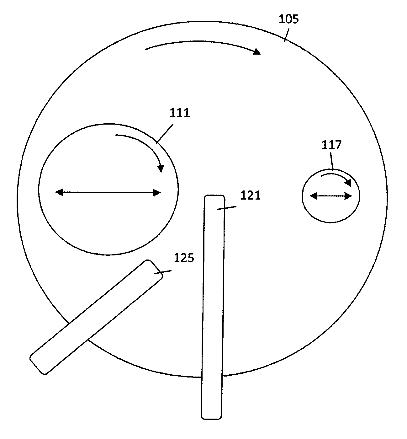
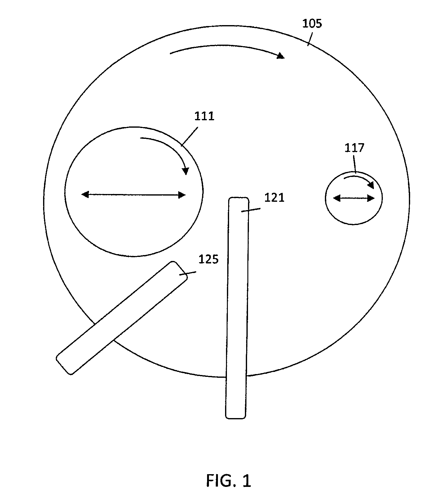
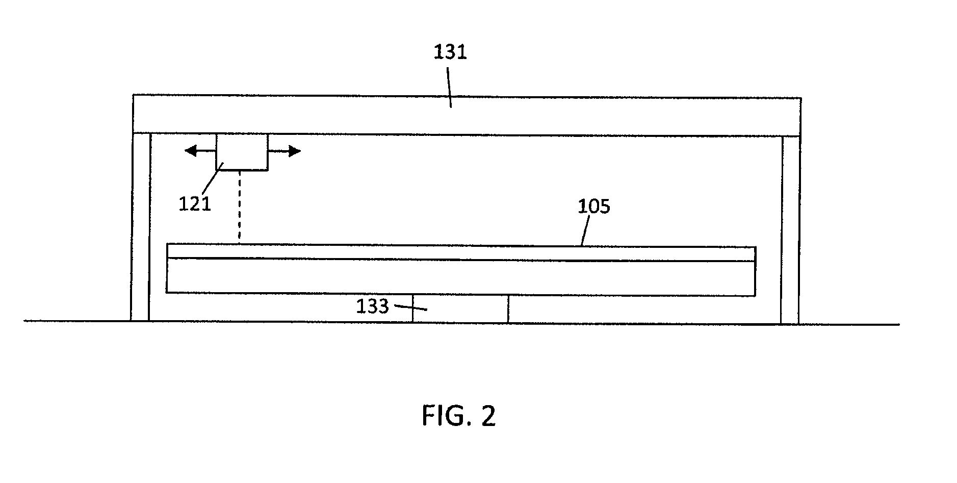
[0022]The present invention is directed towards an improved apparatus and method for maintaining a uniform thickness of a polishing pad during CMP processing. The inventive system monitors the thickness of the CMP polishing pad and makes adjustments to the conditioning pad to maintain a uniform polishing pad thickness. With reference to FIG. 1, the inventive CMP system includes a rotating circular polishing pad 105, a wafer carrier mechanism 111, a conditioning disk 117 and a polishing pad metrology system 121. During CMP processing, abrasive slurry is poured onto the polishing pad 105 by a slurry distribution mechanism 125. The wafer carrier mechanism 111 rotates and moves the wafer over the slurry and across the width of the rotating polishing pad 105. The conditioning disk 117 includes an abrasive surface that contacts the polishing pad 105 and removes wafer particles from the polishing surface. The conditioning disk 117 is pressed against the polishing pad 105 and is swept back ...


PUM

PropertyMeasurementUnit
surface areaaaaaaaaaaa
diameteraaaaaaaaaa
pressureaaaaaaaaaa

Abstract

A chemical mechanical polishing apparatus includes a metrology system that detects the thickness of the polishing pad as semiconductor wafers are processed and the thickness of the polishing pad is reduced. The chemical mechanical polishing apparatus includes a controller that adjusts the rate of material removal of a conditioning disk when areas of the polishing surface are detected that are higher or lower than the adjacent areas of the polishing pad.

Description

FIELD OF INVENTION[0001]The present invention relates to a method and apparatus for conditioning a polishing pad used in chemical mechanical polishing (CMP) to manufacture semiconductor devices.BACKGROUND[0002]A conventional CMP machine includes a rotating polishing pad, a wafer carrier that is coupled and a conditioning disk. During CMP processing, liquid slurry of abrasive particles in a fluid is poured onto the rotating polishing pad and a semiconductor wafer is placed in the wafer carrier. The wafer carrier presses the wafer against the slurry and the rotating polishing pad while the carrier arm moves the wafer across the width of the polishing pad. The chemical reaction with the slurry and the physical erosion due to the contact with the abrasive particles causes material to be removed from the wafer and evens out any irregular topography, making the exposed wafer surface planar. The conditioning disk generally includes a diamond abrasive surface that is moved and rotated again...

Claims


Application Information

Patent Timeline
Patent Type & Authority Patents(United States)
IPC IPC(8): B24B49/12B24B49/18
CPCB24B37/042B24B53/017B24B49/02H01L21/304
Inventor CHANG, SHOU-SUNGCHEN, HUNG CHIHTSAI, STAN DWANG, YUCHUN
Owner APPLIED MATERIALS INC
Why Eureka
Try Eureka