Medical implant detachment systems and methods

a technology of detachment system and medical implant, which is applied in the field of medical implant detachment system and method, can solve the problems of significant morbidity or mortality, increased detachment time, and increased detachment time, so as to reduce the effective distance, reduce the detachment time, and increase the reliability and repeatability of the detachment process.

Active Publication Date: 2012-07-17
STRYKER CORP +1
View PDF34 Cites 66 Cited by
  • Summary
  • Abstract
  • Description
  • Claims
  • Application Information

AI Technical Summary

Benefits of technology

[0010]In accordance with a one aspect of the present inventions, an implant assembly comprises an elongated pusher member, and an implantable device (e.g., a vaso-occlusive device) mounted to the distal end of the pusher member. The implant assembly further comprises an electrolytically severable joint disposed on the pusher member, wherein the implantable device detaches from the pusher member when the severable joint is severed. The implant assembly further comprises a return electrode carried by the distal end of the pusher member in proximity to, but electrically isolated from, the severable joint. For example, the return electrode may take the form of a coil disposed about the pusher member. The return electrode may be carried by the pusher member in such a manner that it remains with the implantable device or remains the pusher member when the severable joint is severed. The implant assembly further comprises a terminal carried by the proximal end of the pusher member in electrical communication with the severable joint. The use of a return electrode on the pusher member decreases the effective distance between the anodic severable joint and cathodic return electrode, thereby decreasing the detachment time and increasing the reliability, repeatability, and uniformity of the detachment process.
[0017]The implant assembly further comprises a terminal carried by the proximal end of the pusher member in electrical communication with the severable joint. The implant assembly further comprises an electrically conductive path extending between the terminal and one of the severable joint and the return electrode, wherein the electrically conductive path includes the electrically conductive sheath. The use of the electrically conductive sheath increases the conductance of the electrically conductive path between the terminal and the severable joint or return electrode, as compared to the case where a standard electrical conductor or the stiffening member is used without the electrically conductive sheath.
[0029]In one embodiment, the insulative sheath is configured to prevent diffusion of an electrolyte from a detachment region between the severable joint and the return electrode. In this manner, the electrically insulative sheath may maintain the ideal electrolytic environment within the detachment region between the severable joint and the return electrode in order to facilitate detachment of the implant assembly. In one embodiment, one or both of the severable joint and the return electrode has a hydrophilic coating, so as to, e.g., facilitate wicking of an electrolyte within the detachment region when desired.
[0032]The method further comprises introducing the medical device within the patient via a pusher member (e.g., through a delivery catheter), and substantially preventing the electrolyte from being diffused away from the detachment region using an electrically insulative sheath. In one embodiment, the insulative sheath is fixably coupled to the pusher member. The method further comprises conveying electrical energy (e.g., direct electrical current) to a joint disposed on the pusher member, and conveying electrical energy from a return electrode carried by the pusher member (e.g., a coil disposed about the pusher member) to induce an electrolytic reaction between the joint and the return electrode. As a result of the electrolytic reaction, the joint is severed to detach the medical device from the pusher member at a target site (e.g., an aneurismal sac) within the patient. In one method, the pusher member is removed from the patient.
[0033]In accordance with yet another aspect of the present inventions, a medical system comprises an implant assembly that includes an elongated pusher member, an implantable device (e.g., a vaso-occlusive device) mounted to the distal end of the pusher member, and an electrolytically severable joint disposed on the pusher member, wherein the implantable device detaches from the pusher member when the severable joint is severed. The medical system further comprises an electrical power supply coupled to the implant assembly, the power supply configured for conveying pulsed electrical energy (e.g., direct electrical current) to the severable joint. By way of non-limiting example, the pulsed electrical energy may have a duty cycle within the range of 5 percent to 20 percent, and a frequency in the range of 5 KHz to 20 KHz. Pulsing the electrical energy delivered to the severable joint will tend to decrease the detachment time and increase the reliability, repeatability, and uniformity of the detachment process.
[0039]The initial electrical energy from the constant current source may quickly break through the oxide layer on the severable joint, whereas the electrical energy from the constant voltage source may minimize bubbling at the detachment region, thereby decreasing the detachment time and increasing the reliability, repeatability, and uniformity of the detachment process.

Problems solved by technology

An aneurysm is a dilation of a blood vessel that poses a risk to health from the potential for rupture, clotting, or dissecting.
Rupture of an aneurysm in the brain causes stroke, and rupture of an aneurysm in the abdomen causes shock.
Cerebral aneurysms are usually detected in patients as the result of a seizure or hemorrhage and can result in significant morbidity or mortality.
While the use of electrolytically detachable vaso-occlusive coils has generally been successful, the period of time needed to detach the vaso-occlusive coils from the pusher wire is relatively long (currently, averaging from 30 to 40 seconds) and variable, resulting in an increase in procedure time.
This problem is compounded by the need to deploy multiple vaso-occlusive coils within the patient.
In addition, the bodily fluid surrounding the sacrificial joint may not be the optimum electrolyte (compared with saline) for inducing an electrochemical reaction in the detachment zone, thereby increasing the detachment time.
Blood environment may also introduce variability in detachment time due to the possibility of blood clotting and the variations in blood constituents amongst patients.
However, an increased voltage may cause bubbling resulting from gas generation byproducts during the electrochemical reaction, which may insulate the detachment zone adjacent the sacrificial joint from the electrolyte, thereby slowing or stopping the electrochemical reaction, and at the least, causing variability in detachment time.
Exiting the microcatheter this far, however, degrades kickback performance (i.e., reaction of the microcatheter in response to detachment of the vaso-occlusive coil is to be minimized) due to the stiffness of the distal end of the pusher wire relative to the stiffness of the vaso-occlusive coil.
In addition, locating the sacrificial joint this far from the distal tip of the microcatheter may cause it to come into contact with previously deployed vaso-occlusive coils, thereby shorting the sacrificial joint through the coils, resulting in an increase and / or variation in the detachment time.
Notwithstanding the bubbling issue, it may sometimes be difficult to ascertain that the sacrificial joint is in contact with the blood, which must occur to initiate the electrochemical reaction and subsequent detachment of the vaso-occlusive coil.

Method used


Image

  • Medical implant detachment systems and methods
  • Medical implant detachment systems and methods
  • Medical implant detachment systems and methods

Examples


Embodiment Construction

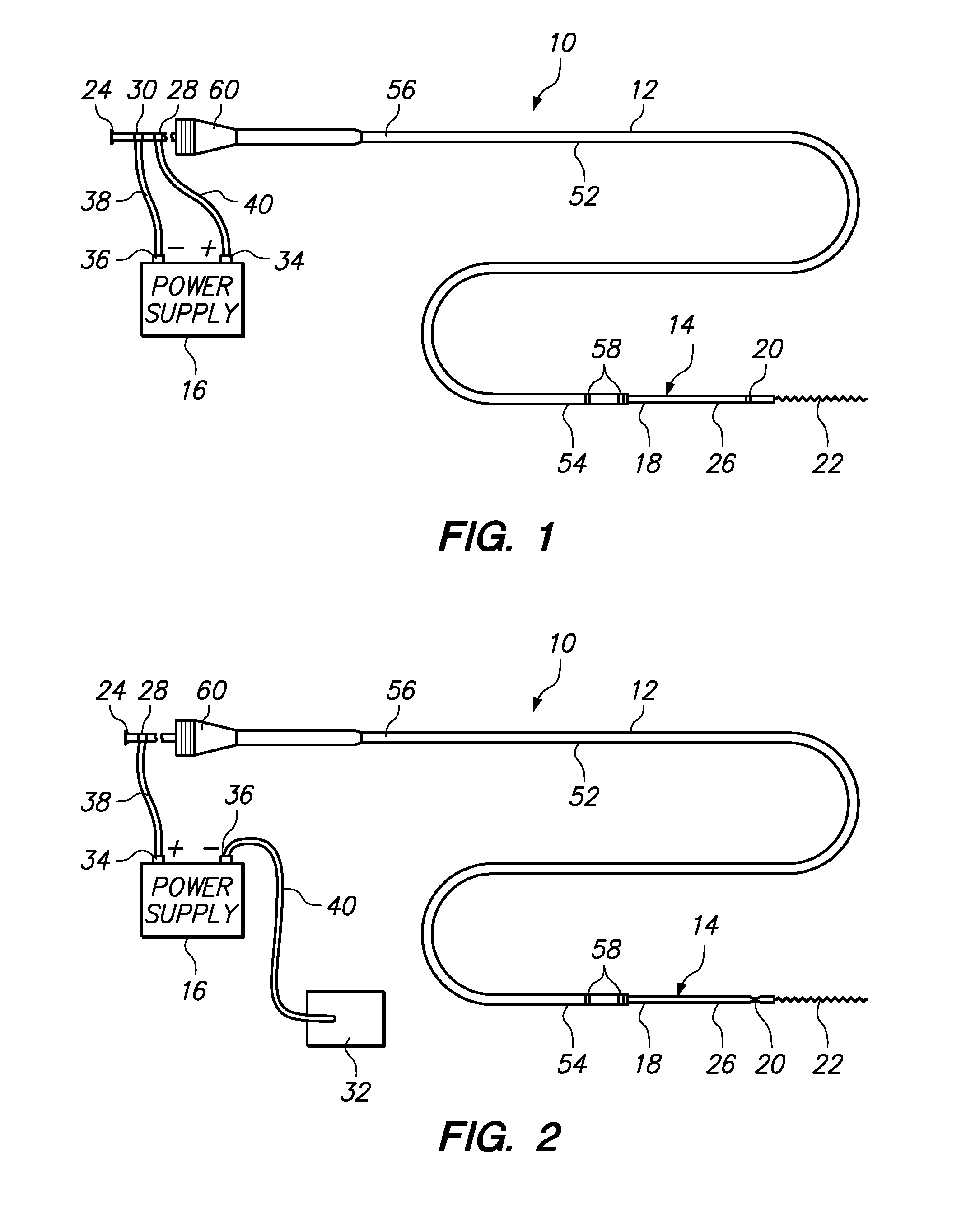
[0058]Referring generally to FIGS. 1 and 2, a medical system 10 constructed in accordance with one embodiment of the present inventions will be described. The medical system 10 is used in vascular and neurovascular indications, and particularly in the treatment of aneurysms, such as cerebral aneurysms. The medical system 10 utilizes an electrolytic detachment means to deploy vaso-occlusive devices, such as helical coils, within an aneurysm. Alternatively, the medical system 10 can be utilized to deploy implantable devices other than vaso-occlusive devices. For example, the medical system can alternatively be used to deploy stents and vena cava filters, which are described in further detail in U.S. Pat. No. 6,468,266, which is expressly incorporated herein by reference.

[0059]To this end, the medical system 10 generally comprises a delivery catheter 12 that can be intravenously introduced within a patient to access a target site within the vasculature, an implant assembly 14 that can ...


PUM


Abstract

An implant assembly comprises an elongated pusher member, and an implantable device (e.g., a vaso-occlusive device) mounted to the distal end of the pusher member. The implant assembly further comprises an electrolytically severable joint disposed on the pusher member, wherein the implantable device detaches from the pusher member when the severable joint is severed, and a return electrode carried by the distal end of the pusher member (e.g., a coil disposed about the pusher member) in proximity to, but electrically isolated from, the severable joint. The implant assembly further comprises a terminal carried by the proximal end of the pusher member in electrical communication with the severable joint.

Description

CROSS-REFERENCE TO RELATED APPLICATIONS[0001]The present application claims the benefit under 35 U.S.C. §119 to U.S. Provisional Application No. 60 / 939,032, filed May 18, 2007, the contents of which are incorporated herein by reference as though set forth in full.FIELD OF THE INVENTION[0002]The invention relates generally to implantable devices (e.g., embolic coils, stents, and filters) having flexible electrolytic detachment mechanisms.BACKGROUND[0003]Implants may be placed in the human body for a wide variety of reasons. For example, stents are placed in a number of different anatomical lumens within the body. They may be placed in blood vessels to cover vascular lesions or to provide patency to the vessels. Stents are also placed in biliary ducts to prevent them from kinking or collapsing. Grafts may be used with stents to promote growth of endothelial tissue within those vessels. As another example, vena cava filters can be implanted in the vena cava to catch thrombus sloughed o...

Claims


Application Information

Patent Timeline
Patent Type & Authority Patents(United States)
IPC IPC(8): A61F2/06
CPCA61B17/12022A61B17/12113A61B17/12154A61B17/12145A61B2017/12063A61B2017/00022
Inventor FORD, RUSSELLMCGILL, SCOTTTEOH, CLIFFORDWILLIAMS, MICHAELRAMZIPOOR, KAMALQUE, LIKEHUANG, ANNOO, ELENAMA, CHRISTINACHU, STELLA
Owner STRYKER CORP
Why Eureka
Try Eureka